Substrate for ink jet head and ink jet head

a technology of ink jet head and ink jet head, which is applied in the direction of printing, etc., can solve the problems of large resistance of electrode wiring, difficult to obtain proper foaming, and difficulty in high-quality recording, so as to prevent the effect of increasing the size and high-quality recording

Inactive Publication Date: 2011-12-13
CANON KK
View PDF16 Cites 8 Cited by
  • Summary
  • Abstract
  • Description
  • Claims
  • Application Information

AI Technical Summary

Benefits of technology

[0011]An object of the present invention is to provide a substrate for an ink jet head which can achieve high-quality recording and prevent increase in size, and an ink jet head including the subject.
[0013]According to the present invention, the potential differences between the energy generating members and the electrode pads can be made equivalent to each other by the resistance elements for adjustment. Therefore, discharge of the ink from each of discharge ports becomes stable to be able to achieve recording with high quality. The electrode wiring extending in the longitudinal direction of the substrate can be disposed with the minimum width, and therefore, increase in the size (width) of the substrate for an ink jet head can be prevented.

Problems solved by technology

Therefore, when the length of the electrode wiring becomes long, the resistance of the electrode wiring becomes large.
Thus, it becomes difficult to obtain proper foaming, and high-quality recording becomes difficult.
However, there is the problem that when the width of the electrode wiring on the substrate becomes large, the size of the substrate also increases.
However, in this case, in order to place the resistance members at the positions illustrated in FIGS. 4A and 4B, the width of the electrode wiring on the substrate also needs to be larger than a certain extent, and there is the problem of increasing the size of the substrate.

Method used


Image

  • Substrate for ink jet head and ink jet head
  • Substrate for ink jet head and ink jet head
  • Substrate for ink jet head and ink jet head

Examples


Embodiment Construction

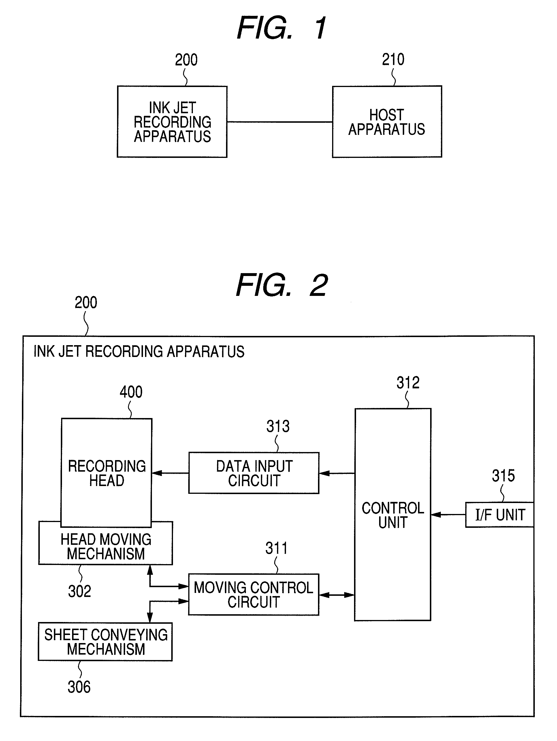
[0020]A mode for carrying out the present invention will be described in detail with reference to the drawings. First, a configuration example of an ink jet recording apparatus to which the present invention is applicable will be described. FIG. 1 is a block diagram illustrating a configuration of an ink jet recording system in the present embodiment. An ink jet recording system of the present embodiment has a host apparatus 210 such as a host computer and an ink jet recording apparatus 200.

[0021]The host apparatus 210 is connected to the ink jet recording apparatus 200, and transmits a record data signal indicating record data such as an image to the ink jet recording apparatus 200. Connection of the host apparatus 210 and the ink jet recording apparatus 200 may be through a cable 220 such as a USB (Universal Serial Bus) cable. Alternatively, connection of the host apparatus 210 and the ink jet recording apparatus 200 may be by radio such as Bluetooth (registered trademark) or infr...


PUM


Abstract

A substrate for an ink jet head is provided with a plurality of energy generating members generating energy used for discharging an ink, an electrode pad which is arranged near a side of the substrate, and is for electrically connecting to an outside of the substrate, a plurality of electrode wirings for electrically connecting the plurality of energy generating members and the electrode pad, and a plurality of resistance elements which are respectively provided at the plurality of electrode wirings. Resistance values of the plurality of resistance elements differ from one another according to resistance values of the electrode wirings provided with the respective resistance elements.

Description

BACKGROUND OF THE INVENTION[0001]1. Field of the Invention[0002]The present invention relates to a substrate for an ink jet head (hereinafter, also simply called as “substrate”) provided with energy generating members generating energy used for discharging an ink, and an ink jet head including the substrate.[0003]2. Description of the Related Art[0004]Japanese Patent Application Laid-Open No. S59-095154 discloses an ink jet recording apparatus of a method of vertically discharging an ink to a substrate from an ink supply port.[0005]A substrate loaded on an ink jet recording apparatus of this kind has an ink supply port forming a rectangular opening so as to penetrate through a center of the substrate. The substrate supplies an ink or multicolor inks with high density to a discharge port from an ink supply port. A heat generating resistance element is arranged along the long side of the ink supply port, and is connected with an electrode pad with wirings to receive supply of a curren...

Claims


Application Information

Patent Timeline
Patent Type & Authority Patents(United States)
IPC IPC(8): B41J2/05
CPCB41J2/04506B41J2/04543B41J2/04565B41J2/0458B41J2/14072B41J2/1601B41J2/1628B41J2/1629B41J2/1631B41J2/1642B41J2/1646
Inventor HATSUI, TAKUYAKOMURO, HIROKAZUSHIBATA, KAZUAKI
Owner CANON KK
Why Eureka
Try Eureka