
Food dispenser

a food dispenser and automatic technology, applied in the field of food dispensers, can solve problems such as prone to mould, and achieve the effects of repeatable accurate feeding of feed rations, detection of any erroneous operation, and quick and easy optimization

Inactive Publication Date: 2011-12-13
LALIBERTE JEAN CHARLES
View PDF37 Cites 22 Cited by
  • Summary
  • Abstract
  • Description
  • Claims
  • Application Information

AI Technical Summary

Benefits of technology

"The invention is an automatic food dispenser that is easy to adjust and can dispense pelletized or powdered dry food for animal husbandry. It includes a food receiving module, a metering module, and a discharge module. The metering module has an impeller with rotating arms that dispense the food from the upper part of the dispenser. The impeller is driven by a power drive unit and a magnetic field sensor detects its rotation. The dispenser is controlled by an electronic control unit that can program the feed schedule and detect any errors in the metering module. The three main modules of the dispenser are easily assembled and disassembled. The invention provides a fast and easy way to optimize the dispensing of dry food for animal husbandry."

Problems solved by technology

a) they are generally specifically adapted for only one type of dry food material for animals, either pelletized or powdered / granulated dry food;
b) their mode of operation for dispensing predetermined amount of feed is generally based on a timed operation of a rotating element within the dispenser, and without monitoring means on the actual dispensing of the food;
c) they are generally not readily designed to be quickly and easily disassembled for periodic cleaning. Thus, moisture trapped in dry food dust accumulated in compact mechanical assemblies of the dispenser is prone to develop mould, a generally unacceptable problem in industrial husbandry of animals destined for human consumption.

Method used


Image

  • Food dispenser
  • Food dispenser
  • Food dispenser

Examples


Embodiment Construction

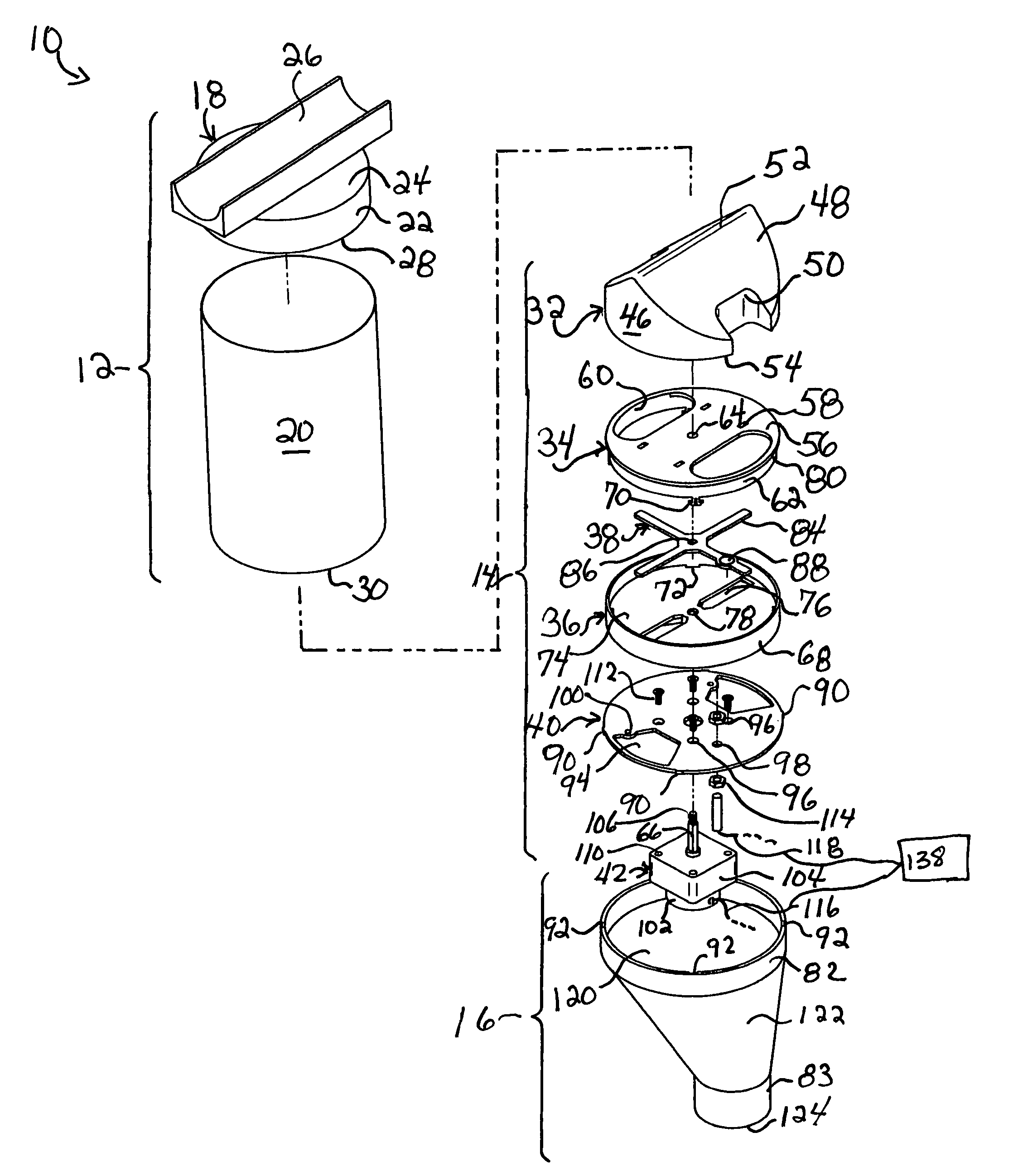
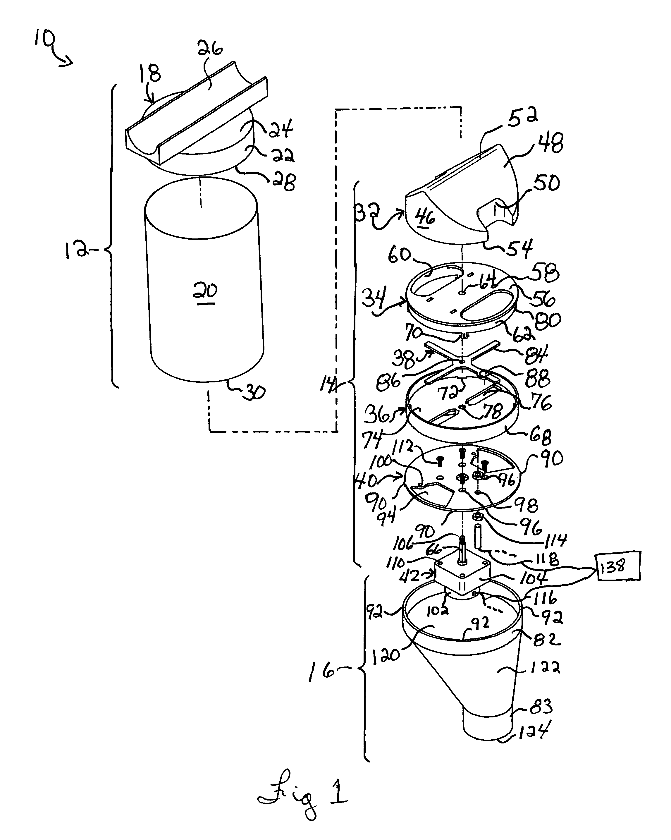
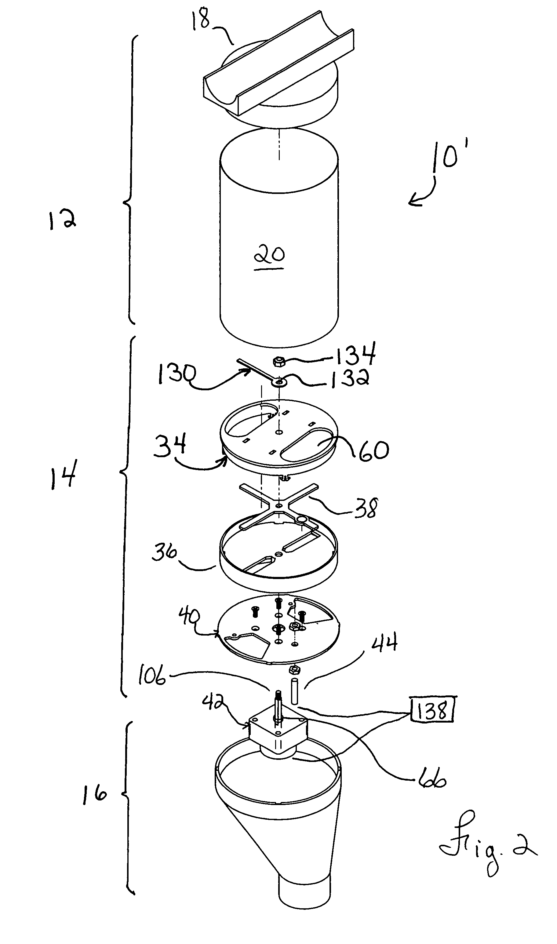
[0033]FIG. 1 shows an embodiment of the food dispenser 10 of the present invention that is configured for optimized dispensing of pelletized dry food (not shown in the drawings) for animals. The food dispenser 10 generally comprises a food receiving module 12 for receiving the food, a metering module 14 for metering a quantity of the food to dispense, and a discharge module 16 operatively coupled to the metering module 14 for receiving the food from the food metering module 14 and dispensing the food, for example by conveying the dispensed food into a suitable receptacle such as a feed dish or the like (not shown). In some embodiments of the invention, as shown in FIG. 1, the food receiving module 12 takes the form of a hopper module for temporarily storing animal feed to be dispensed.

[0034]The food receiving module 12 generally consists of a removable cover 18 and an upstanding, open-ended cylindrical body 20. The cover 18 is represented by a cylindrical side wall 22 closed at a to...


PUM


Abstract

A food dispenser for dispensing dry food, the food dispenser comprising: a food receiving module for receiving the food; a metering module for metering a quantity of the food to dispense, the metering module including an impeller having at least one arm defining a vane, the impeller being rotatably mounted in the metering module, the metering module also including a power drive unit operatively coupled to the impeller for selectively rotating the impeller; a discharge module operatively coupled to the output port for receiving the food from the output port and dispensing the food; an impeller rotation detector operatively coupled to the impeller for detecting a rotation of the impeller when the power drive unit is used to rotate the impeller. The metering module is configured and sized to discharge a predetermined quantity of the food when the impeller rotates over a predetermined rotation angle. The impeller rotation detector detects that the impeller has rotated over the predetermined rotation angle after the power drive unit has been energized to detect dispensing of the predetermined quantity of the food.

Description

[0001]This application claims priority from GB Patent Application Number 0819220.5 on Oct. 21, 2008.FIELD OF THE INVENTION[0002]The present invention relates generally to food dispensers and, more particularly, to an automatic dry food dispenser for feeding animals.BACKGROUND[0003]Automatic food dispenser for feeding animals, such as automatic dispensers specifically designed for pet animals, as well as the more sturdy type designed for industrial husbandry, are known in the art and are useful for automatically dispensing food material, such as pelletized or powdered dry food to animals.[0004]Such automatic food dispensers of the prior art generally comprise three main elements: a container, or hopper compartment, for temporarily storing the dry food to be dispensed to the intended animal, a power driven feed transfer chamber for dispensing a metered amount, or ration, of dry food on a timely basis, and a conveying means for conveying the dispensed ration to a suitable receptacle su...

Claims


Application Information

Patent Timeline
Patent Type & Authority Patents(United States)
IPC IPC(8): A01K5/02
CPCA01K5/0275
Inventor LALIBERTE, JEAN-CHARLES
Owner LALIBERTE JEAN CHARLES
Learn More