
Wireless communication apparatus, wireless communication method, and computer program

a wireless communication and wireless communication technology, applied in the direction of receiving receiver monitoring, electromagnetic wave modulation, polarisation/directional diversity, etc., can solve the problems of channel misrecognition, degradation of the characteristics of rf circuit chips, and imbalances in the transfer coefficients between the transmit and receive branches, so as to prevent error and curtail estimation error

Inactive Publication Date: 2011-11-22
SONY CORP
View PDF13 Cites 41 Cited by
  • Summary
  • Abstract
  • Description
  • Claims
  • Application Information

AI Technical Summary

Benefits of technology

The patent text describes a wireless communication apparatus and method that can optimize data transmission using a spatial multiplexing (MIMO) communication technique. The apparatus includes multiple antennas and a calibration processor to correct phase and amplitude imbalances among the antennas. The calibration processor can multiply receive signals in each receive branch by antenna calibration coefficients to compensate for the imbalances. The apparatus can also use a channel matrix estimator to estimate a transmit beamforming matrix and a transmit beamforming matrix. The final estimated value takes into account the multiplication by correction coefficients to avoid errors in estimating likelihood information, noise power, and channel waveform equalization values. The wireless communication apparatus can conduct antenna calibration only when the apparatus is standing by to receive a packet used for antenna calibration. The technical effects of the patent text include improved transmission capacity, increased frequency utilization efficiency, and reduced power loss.

Problems solved by technology

Meanwhile, in multi-antenna communication using a plurality of transmit and receive antennas (as typified by MIMO and adaptive arrays), there exist imbalances in the transfer coefficients (i.e., the phase and amplitude) among the transmit and receive branches.
In the digital processor on the receive side, the combination of the spatial transfer coefficients and the transfer coefficients in the analog unit within the apparatus are recognized as channels, and thus branch imbalances in the analog unit can lead to channel misrecognition.
If there are large fluctuations in the gain in each transmit branch, then the power loss accompanying the multiplication by the calibration coefficients also becomes large, resulting in degradation in the characteristics of RF circuit chips, where fluctuations are small.
For this reason, there is concern that decoding performance will degrade if the noise estimation is poor.
However, when respectively multiplying the receive signals in each receive branch by calibration coefficients in order to compensate for phase and amplitude imbalances existing among transmit and receive branches as described above, the above corresponds to invalid gain being applied among branches.
For this reason, in a system that conducts antenna calibration on the receive side, the occurrence of errors in the estimation of the SNR and the likelihood information performed when calibrating is dependent on the noise estimation method, leading to concerns regarding the degradation of reception characteristics.

Method used


Image

  • Wireless communication apparatus, wireless communication method, and computer program
  • Wireless communication apparatus, wireless communication method, and computer program
  • Wireless communication apparatus, wireless communication method, and computer program

Examples


Embodiment Construction

[0053]Hereinafter, embodiments of the present invention will be described in detail and with reference to the accompanying drawings.

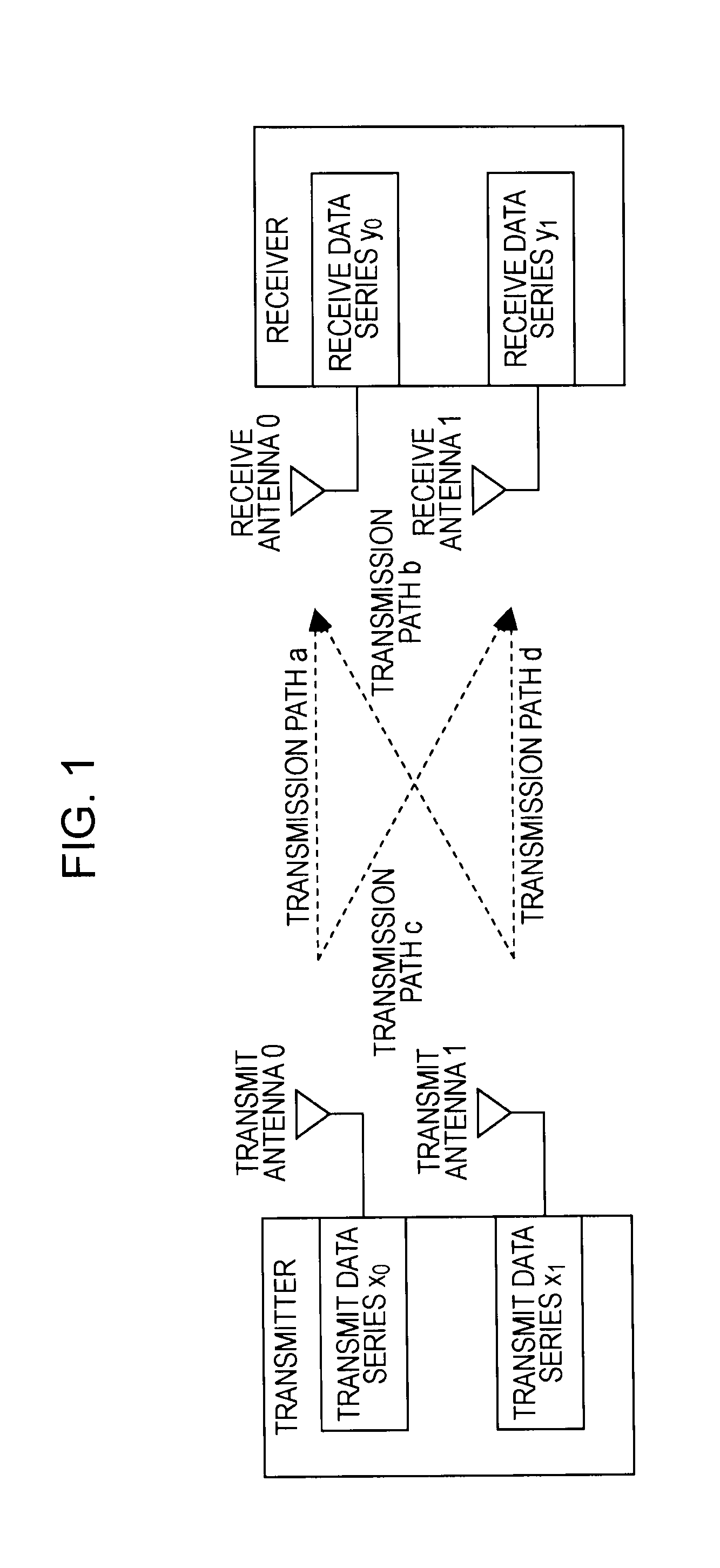
[0054]MIMO is a communication method that realizes a spatially multiplexed stream by providing a plurality of antenna elements at both the transmitter and the receiver. On the transmit side, a plurality of transmit data is multiplexed by performing space-time coding, distributed across a plurality of transmit antennas, and then transmitted on a channel. Likewise, on the receive side, a receive signal received by a plurality of receive antennas via the channel is separated into the plurality of transmit data by performing space-time decoding. Thus, the original data can be obtained without inter-stream cross-talk. By means of a MIMO communication method, the transmission capacity can be increased in accordance with the number of antennas, and without increasing the frequency band. As a result, an improved data transfer rate can be achieved.

[0055]FIG. 1 s...


PUM


Abstract

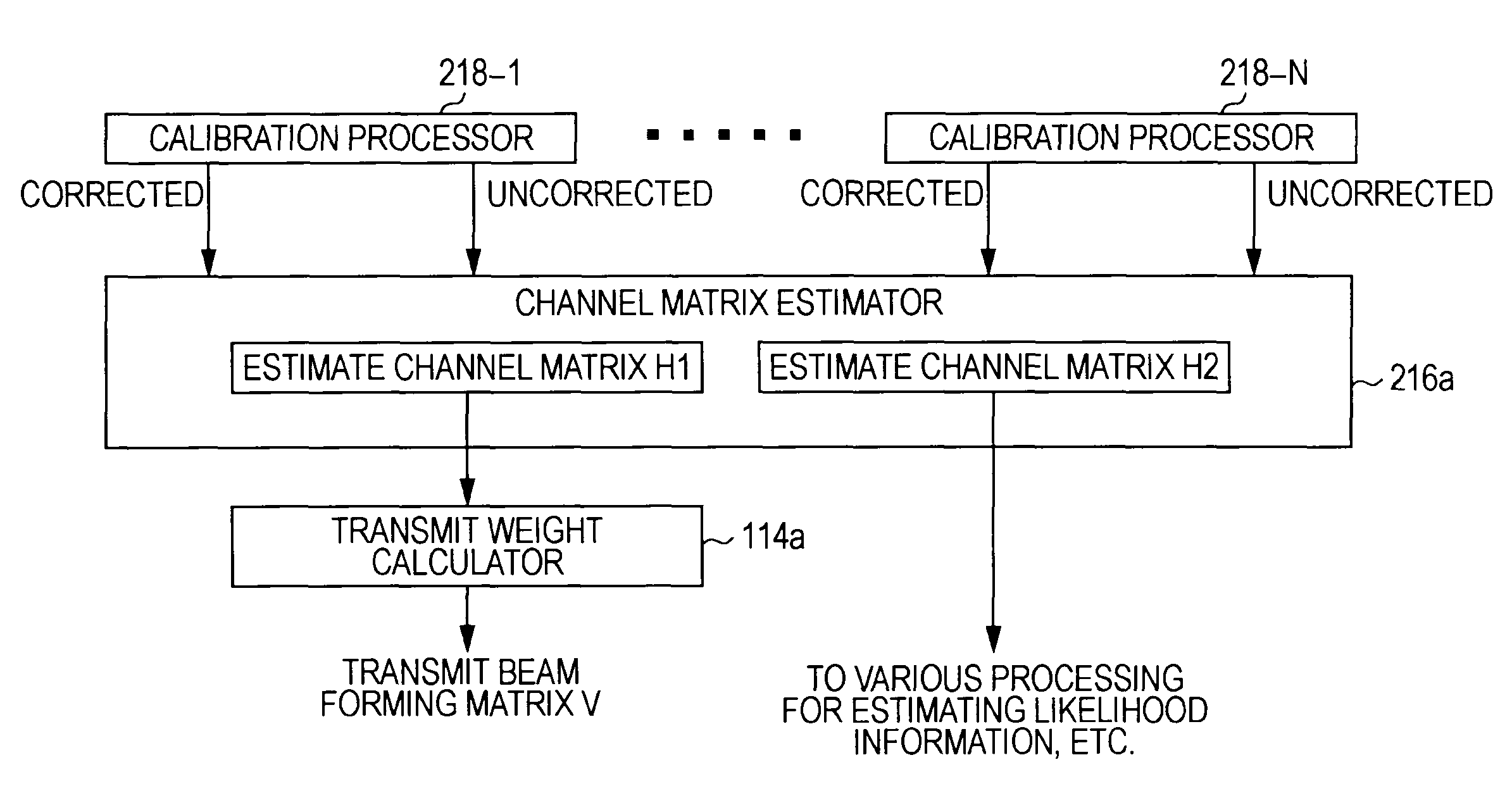
A wireless communication apparatus compensates for phase and amplitude imbalances existing among transmit and receive branches, while also preventing likelihood information and SNR estimation error produced by such imbalance compensation. In an apparatus having a plurality of transmit and receive antennas and respective branches for each antenna, a calibration processor multiplies receive signals in each receive branch by antenna calibration coefficients, in order to correct phase and amplitude imbalances existing among the receive branches. A transmit beamforming matrix estimator then estimates a transmit beamforming matrix by using the multiplied receive signals. An estimator then solves for estimated values such as the noise power, likelihood information, and channel waveform equalization values for each receive branch, and in addition, derives a final estimated value that takes the multiplication by correction coefficients into account when averaging the estimated values for each receive branch or when computing a weighted average according to likelihood.

Description

BACKGROUND OF THE INVENTION[0001]1. Field of the Invention[0002]The present invention relates to a wireless communication apparatus, a wireless communication method, and a computer program whereby data is communicated with increased transmission capacity by means of a spatial multiplexing (MIMO) communication technique using paired transmitters having a plurality of antennas each. More particularly, the present invention relates to a wireless communication apparatus, a wireless communication method, and a computer program whereby spatially multiplexed communication is conducted by compensating for phase and amplitude imbalances existing among transmit and receive branches, and thereby obtaining a suitable channel matrix.[0003]2. Description of the Related Art[0004]Wireless networks are now the subject of much attention, being systems free from the wiring involved in wired communication methods of the past. Specifications such as IEEE 802.11 (Institute of Electrical and Electronics E...

Claims


Application Information

Patent Timeline
Patent Type & Authority Patents(United States)
IPC IPC(8): H04B1/38H04L5/16H04B7/04H04J11/00H04J99/00
CPCH04B17/21H04L25/03343H04B17/12H04L25/03006H04L1/0025H04L1/0068H04L1/0071H04L1/0618H04L2025/03414H04L2025/03426
Inventor SAWAI, RYOUTAKANO, HIROAKI
Owner SONY CORP
Learn More