
Electrooptic device, scanning-line driving circuit, method for driving the same, and electronic device

a technology of scanning-line driving circuit and electronic device, which is applied in the direction of color television details, instruments, computing, etc., can solve the problems of reduced images with so-called disclination (inferior orientation), difference in display between the upper end and the lower end of the display screen, and low moving image display characteristi

Inactive Publication Date: 2011-11-22
SEIKO EPSON CORP
View PDF16 Cites 12 Cited by
  • Summary
  • Abstract
  • Description
  • Claims
  • Application Information

AI Technical Summary

Benefits of technology

This approach enhances moving-image display characteristics by reducing display differences between the upper and lower parts of the screen, eliminating afterimages, and optimizing voltage writing time, thereby improving the overall performance of electrooptic devices.

Problems solved by technology

Such electrooptic devices that form reduced images have the problem of so-called disclination (inferior orientation) because of the extremely narrow gap between the pixels.
However, the plane inversion has the problem of causing a difference in display between the upper end and the lower end of the display screen.
This increases the persistence of vision to cause the outline of moving areas to blurs thus posing the problem of low moving-image display characteristic.
Such a problem of low moving-image display characteristic is not limited to the area scanning drive system but also occurs in display devices having a hold-type display characteristic such as liquid crystal displays.

Method used


Image

  • Electrooptic device, scanning-line driving circuit, method for driving the same, and electronic device
  • Electrooptic device, scanning-line driving circuit, method for driving the same, and electronic device
  • Electrooptic device, scanning-line driving circuit, method for driving the same, and electronic device

Examples


Embodiment Construction

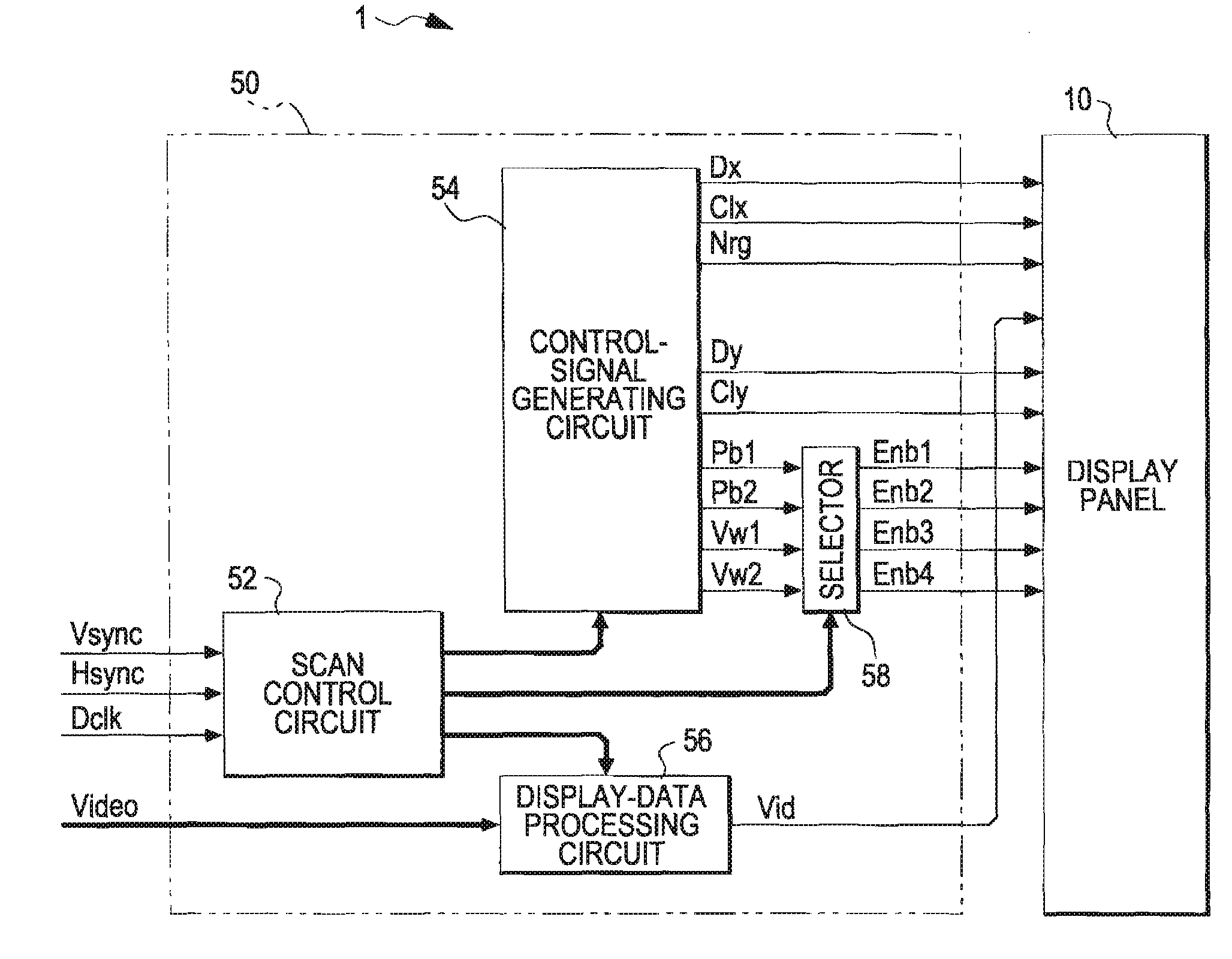
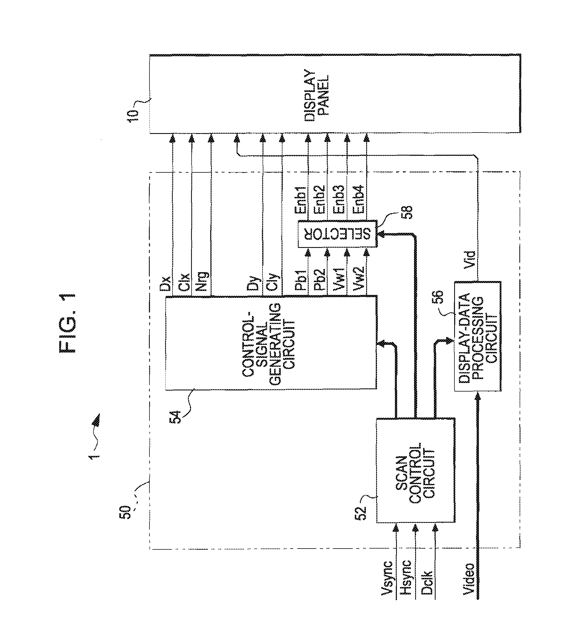
[0035]Embodiments of the invention will be described with reference to the drawings. FIG. 1 is a block diagram illustrating the configuration of an electrooptic device according to an embodiment of the invention.

[0036]As shown in the illustration, the electrooptic device 1 is mainly composed of a display panel 10 and a processing circuit 50. The processing circuit 50 is a circuit module for controlling the operation of the display panel 10 in response to the application of a data signal Vid, and is connected to the display panel 10 with, e.g., a flexible printed circuit (FPC) board.

[0037]Specifically, the processing circuit 50 includes a scan control circuit 52, a control-signal generating circuit 54, a display-data processing circuit 56, and a selector 58. The scan control circuit 52 controls the control-signal generating circuit 54 and the display-data processing circuit 56 in synchronism with a vertical synchronizing signal Vsync, a horizontal synchronizing signal Hsync, and a do...


PUM


Abstract

An electrooptic device is driven so that row groups of the pixels that are made black in a first precharge period and a row group of the pixels that are made black in a second precharge period are next to each other.

Description

BACKGROUND[0001]1. Technical Field[0002]The present invention relates to a technique for improving the moving-image display characteristic of an electrooptic device that employs what is called an area scanning drive system.[0003]2. Related Art[0004]Projectors are becoming widely used which form reduced images using an electrooptic device such as a liquid crystal device and which project the reduced images on enlarged scale with an optical system. Such electrooptic devices that form reduced images have the problem of so-called disclination (inferior orientation) because of the extremely narrow gap between the pixels. The disclination can be prevented by plane inversion (also referred to as frame inversion) in which adjacent pixels are given the same polarity. However, the plane inversion has the problem of causing a difference in display between the upper end and the lower end of the display screen.[0005]To solve the problem of display difference, what is called an area scanning driv...

Claims


Application Information

Patent Timeline
Patent Type & Authority Patents(United States)
IPC IPC(8): G09G3/36
CPCG09G3/2096H04N9/312G09G3/001G09G3/3648G09G3/3677G09G2300/08G09G2310/0251G09G2310/0256G09G2310/0267G09G2310/0275
Inventor ISHII, KENYA
Owner SEIKO EPSON CORP
Learn More