Eureka AIR delivers breakthrough ideas for toughest innovation challenges, trusted by R&D personnel around the world.

Signal repeater system

a repeater and signal technology, applied in the field of signal repeater systems, can solve the problems of large physical dimensions, high supply current draw, and contribute to a substantial reduction of the overall bandwidth of the system

Inactive Publication Date: 2011-11-15
VAVIK GEIR MONSEN
View PDF13 Cites 182 Cited by
  • Summary
  • Abstract
  • Description
  • Claims
  • Application Information

AI Technical Summary

Benefits of technology

[0007]It is one main object of the present invention to provide solutions that in a low cost and production friendly way secures repeatability, stable operation and maximum signal dynamics for analogue high frequency repeaters in systems specifically for one and two way wire bound digital communication, digital “streaming”, digital “multicast”, digital return channel for other systems as in digital point to multiple point and all similar systems, but the invention also has important corresponding applications for wireless transmissions. Besides, one purpose of the invention is to keep power consumption low with the help of simplicity in design. An additional object of the invention is for it to be installation friendly. The object of the invention is also to offer redundancy, improved stability and a wider scope of application for the inventions described in the publications NO20001057, NO20010132, NO20020112, PCT / NO01 / 00079, PCT / NO03 / 00004. Further objects of the invention are achieved by improvement of the stability criteria for repeaters with gain within the same frequency band both with gains less than port isolation and gain larger than port isolation. A similar object of the invention is achieved with solutions regarding duplex conditions. Still other objects of the invention are achieved with solutions that reduce mutual interference between repeaters, beating between repeaters and interference from echo or reflections. A further object of the invention is to be able to realise practical solutions for directional discrimination and conveying large bandwidths on single conductors like power lines. One object of the invention is also to allow the solutions by the invention to be utilised in an adaptive way where the adaptivity is controlled by local intelligence or by central intelligence. A further object of the invention is to be able to combine several methods of achieving isolation between ports, to reflections and to other repeaters. To a skilled person of the art it will be apparent that other objects of the invention are obvious.THE INVENTION
[0012]When determining the physical distance and position for repeaters generally is at liberty as in the cases of open power lines or their associated ground lines the invention permits the introduction of added isolation in the same frequency channel by making every second distance between repeaters larger causing a resulting, additional useful attenuation which is conveniently combined into isolation and required signal dynamics.
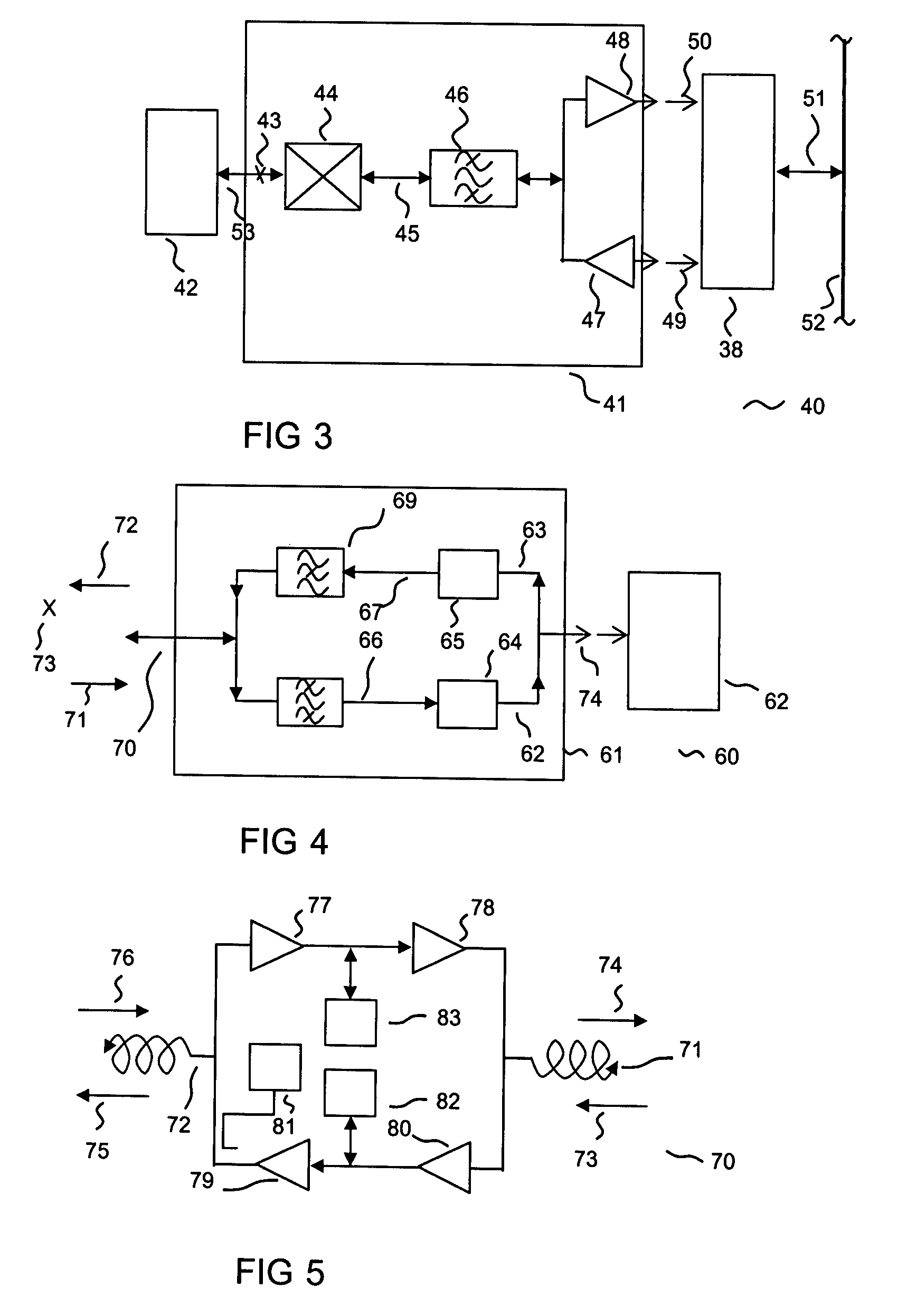
[0013]One example of repeater is described in patent publications NO20001057, NO20010132, NO20020112, PCT / NO01 / 00079, PCT / NO03 / 00004 is a double, super heterodyne repeater where there exists a signal intermediate frequency which is favourable as a common intermediate frequency together with an adapter for a wireless or other high frequency based modem as for example a IEEE802.11x node, Docsis node or other type node. The invention facilitates bi-directional mixing of the microwave frequency of the wireless modem into this intermediate frequency in such a manner that a modem or a node is connected at any point where there is a repeater of the type referred to and that matches this intermediate frequency. The invention also describes an adapter solution where in addition to frequency converting a bypass signal path is arranged using any kind of stop frequency band arrangement for the frequency converted frequency band to achieve acceptable duplex specifications. To improve upon duplex characteristics for high requirements in dynamics the invention can utilise triple- or higher order super heterodyne, thus allowing receiver and transmitter having different intermediate frequency to avoid local oscillators reducing dynamics.
[0015]The invention in one embodiment has in a given repeater point two repeaters in the same frequency band where the repeaters satisfy today's coexistence requirements and where the two repeaters utilise different frequency bands for the two signal directions. In addition the invention can apply opposite antenna polarisation for the different signal ports. Polarisation may be circular or linear and may be in the form of antenna; antenna element or probe and a reflector can be used. In one embodiment the repeaters can be installed on different conductors of a power transmission line to separate the two signal directions. Probing and excitation by the help of the “antennas” is relatively none critical whereas the coupling element does not have to be too close to the conductor but in fact may be installed with a practical spacing to the conductor allowing the coupling element to be looking along the conductor line. The coupling elements will look in the respective directions from the repeaters. In this way it is possible to install repeaters that do not make direct galvanic contact with the high voltage conductor.

Problems solved by technology

The resulting conversion that takes place within them causes high supply current draws and they tend to be of large physical dimensions.
In addition each repeater contributes to a substantial reduction of the overall bandwidth of the system and always introduces problematic latencies that either excludes or complicates certain modern, time critical telecommunication services.
There are physical limitations as well to which extent technologies within digital repeaters can be developed for large bandwidths.
With known semiconductor types there are physical limits to how much it is possible to reduce current consumption at high processing speeds being limited, amongst other factors, by the lower limit of transistor bias and clock frequencies.
Such concepts are likewise not inexpensive in production as for instance due to their obligation to utilise the newest and most expensive technology available.
Such technologies are therefore likely to be quickly replaced by new generations leading to hi write-off costs.
As a consequence, it is too expensive and impracticable to use a sufficient number of such repeaters for, as an example sustaining signal levels on cables or for wireless coverage in an area where line of sight obstructions are significant.
It has been claimed that analogue repeaters as opposed to digital repeaters accumulate noise.
These are conclusions with substantial flaws in addition to the fact that digital repeater systems will accumulate noise that gradually reduces symbol bandwidth in addition to the band width reduction being caused by the latency associated with each repeater.
In wire bound systems certain control of this may usually be exercised in wireless systems varying reflection parameters are often a larger problem.
However, in large scale context this is too expensive and additionally it is often impracticable.
The consequences of insufficient attenuation between input and output signal in signal repetition using frequency transposing is duplex interference.
The consequences under the mentioned, none optimal conditions as a result of reflections or lack of attenuation may be that stability requirements cannot be sustained for signal repetition within the same channel.
Phase is affected by the complex impedance that the gain block (amplifier) looks at and by the attenuation between ports of a multiple port gain block Analogue gain has to a large extent been abandoned in modern networks due to the difficult task of combining stability and satisfactory gains.
It is especially difficult to make solutions that are both repeatable and possibly producible in large quantities or large systems.
For some modulation types problems with frequency beating can occur even with relatively large attenuation.
Previously published solutions are not able to satisfy attenuation requirements and these solutions are either not practically applicable or have only limited applications as for example in none linear systems, for example frequency modulation for rather limited bandwidths.

Method used


Image

  • Signal repeater system
  • Signal repeater system
  • Signal repeater system

Examples


Embodiment Construction

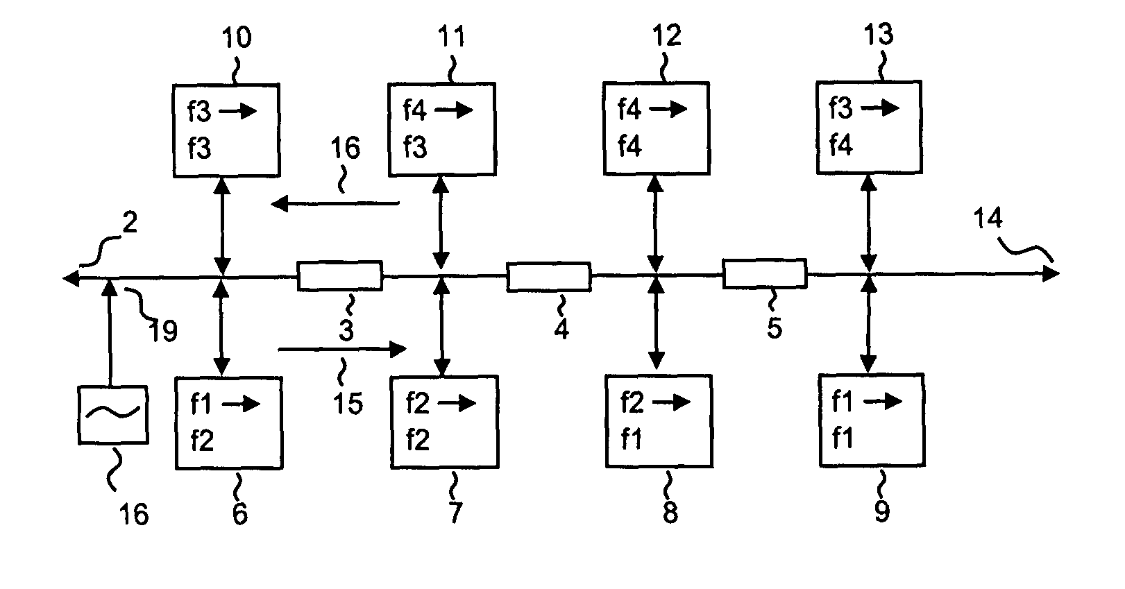
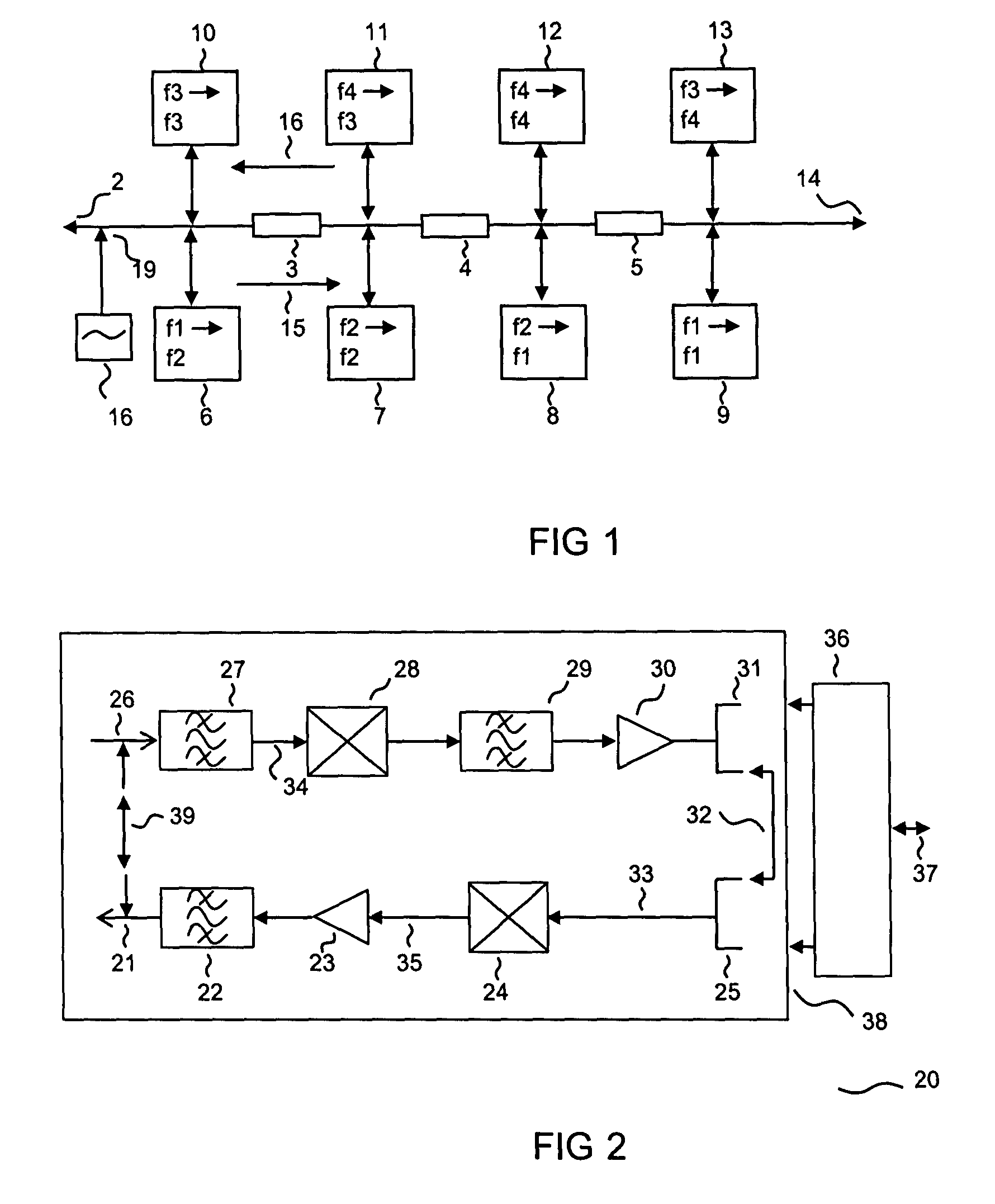
[0033]FIG. 1 illustrates how the invention in a repeater system 1 or a repeater cascade 1 makes use of frequency transposing repeaters where isolation against echo between repeaters is made redundant by the use of three frequency bands, f1, f2, f2 for each information channel, possibly each signal direction in use. The figure shows in more detail how the invention makes use of a repeater cascade 1 with the help of frequency transposing repeaters 6, 8 in combination with repeaters that amplifies within the same channel 7, 9 by applying only two frequency bands, f1 and f2 for on and the same information channel. This is achieved in a symmetrical system by repeater 6 frequency shifting from frequency f1 to f2. The nest repeater 7 repeats the signal within the same frequency band, f2. The next repeater 8 repeats by frequency shifting to f1. Further on the sequence is repeated starting with the subsequent attenuation 5 and repeater 9. In this way echo for example into one repeater 6 from...


PUM


Abstract

The present invention concerns analog signal repeater system solutions of the general kind. It concerns in particular stability with analog signal repeater systems.

Description

INTRODUCTION[0001]The present invention concerns analogue signal repeater system concepts of the general type as explained in the preamble of the appended claim 1, as well as analogue signal repeater as described in appended claim.BACKGROUND[0002]During the last 20 years, analogue, high frequency repeaters in data communication systems have been neglected in favour of digital concepts. Analogue gain may be realised with analogue or digital signal processing methods and are characterised firstly by their full or part transparency. They offer an amplified, analogue representation of the input signal to give a near sustained bandwidth and very low latency even at very large system bandwidths. Digital repeaters are not transparent and are commonly based on just one type of modulation as well as one type of communication protocol, which again is likely to be of proprietary character. The resulting conversion that takes place within them causes high supply current draws and they tend to b...

Claims


Application Information

Patent Timeline
Patent Type & Authority Patents(United States)
IPC IPC(8): H04B7/14H04J3/08H04J1/10H03F3/181H03F3/189H04B3/20H04B3/36H04B3/38H04B3/56H04B3/58H04B7/015
CPCH04B3/36H04B3/56H04B3/58H04B2203/5425H04B2203/5441H04B2203/5445H04B2203/5479H04B2203/5483H04B2203/5491
Inventor VAVIK, GEIR MONSEN
Owner VAVIK GEIR MONSEN
Why Eureka
Eureka Blog
Learn More