
Power connector having a contact configured to transmit electrical power to separate components

a technology of electrical power transmission and power connector, which is applied in the direction of coupling contact members, coupling device connections, electric discharge lamps, etc., can solve the problems of inability the original configuration of the computer system may not be able to meet the increased power demand, and the inability to add an electrical component to an existing computer system

Active Publication Date: 2011-11-15
TYCO ELECTRONICS LOGISTICS AG (CH)
View PDF7 Cites 45 Cited by
  • Summary
  • Abstract
  • Description
  • Claims
  • Application Information

AI Technical Summary

Benefits of technology

[0004]In one embodiment, a power connector is provided that includes a connector housing having a mating side configured to engage an electrical connector. The connector housing also has a mounting side configured to interface with a circuit board. The connector housing includes a housing cavity that opens to the mating side. The power connector also includes a power contact that is held within the housing cavity and configured to engage the electrical connector. The power contact i...

Problems solved by technology

However, introducing updated electrical components into an existing electrical system may present challenges.
For example, if the new electrical component requires additional power to operate, the original configuration of the computer system may not be able to satisfy the increased power demand.
However, adding an electrical component to an existing computer system may be impractical since the computer system was particularly configured for the other electrical components.

Method used


Image

  • Power connector having a contact configured to transmit electrical power to separate components
  • Power connector having a contact configured to transmit electrical power to separate components
  • Power connector having a contact configured to transmit electrical power to separate components

Examples


Embodiment Construction

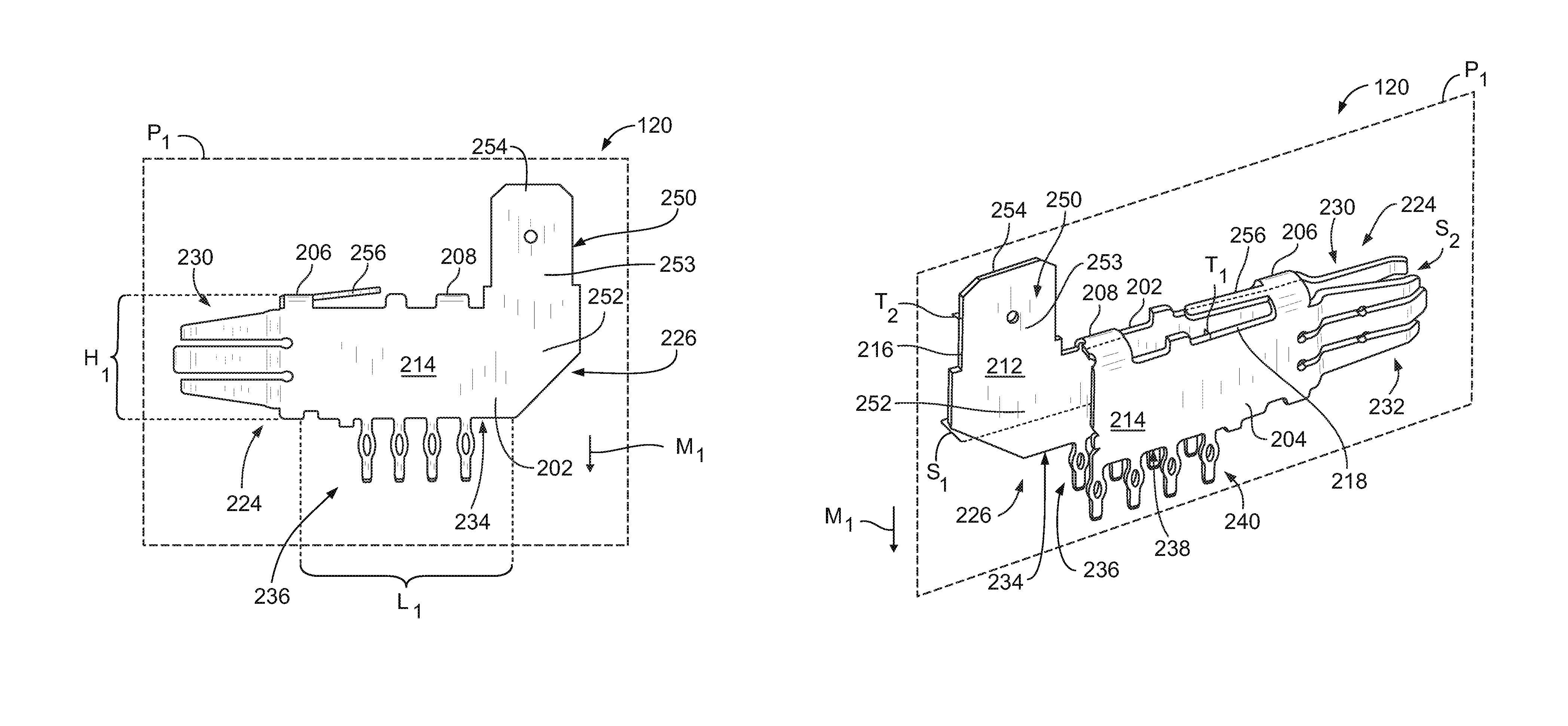
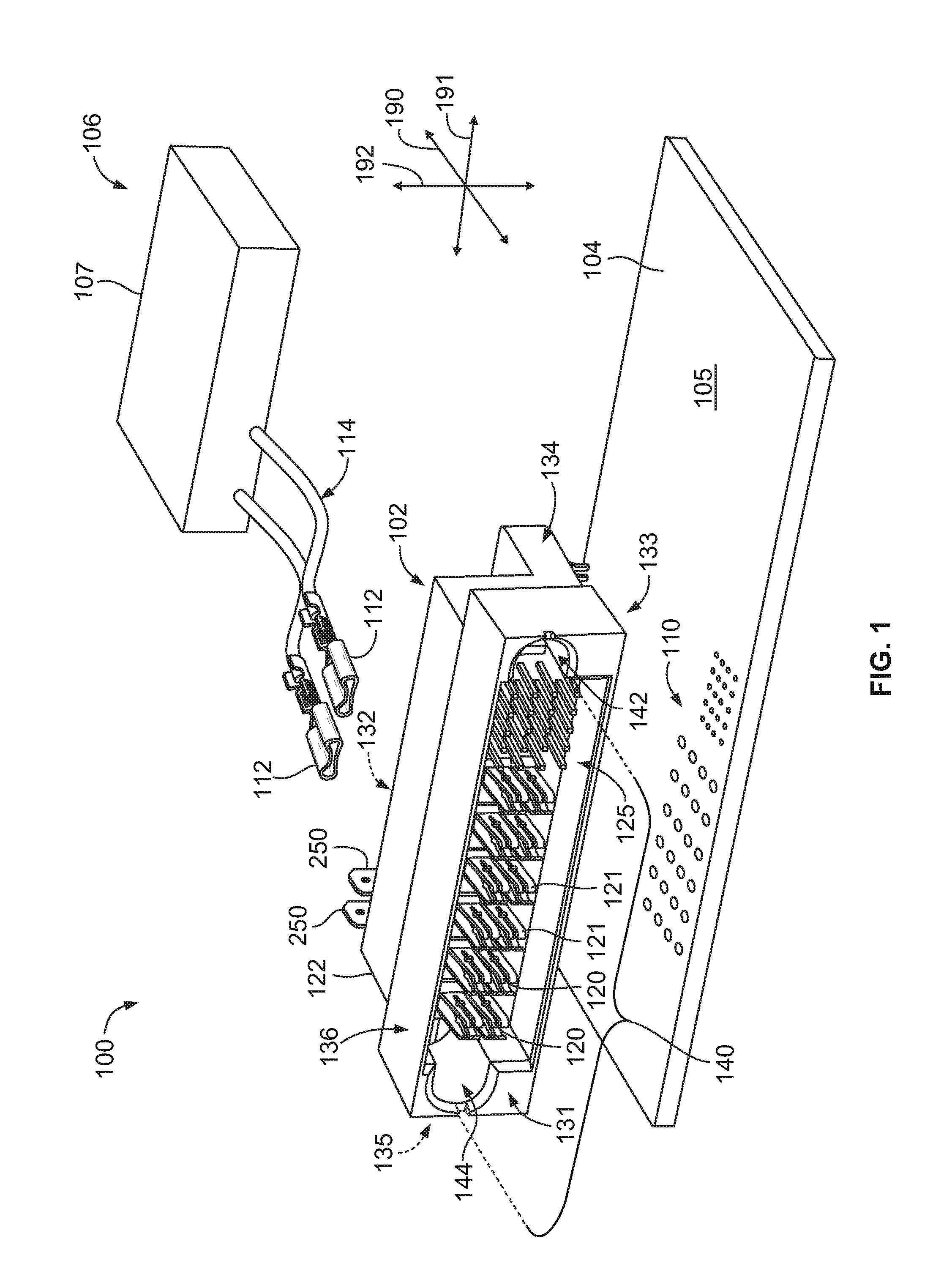
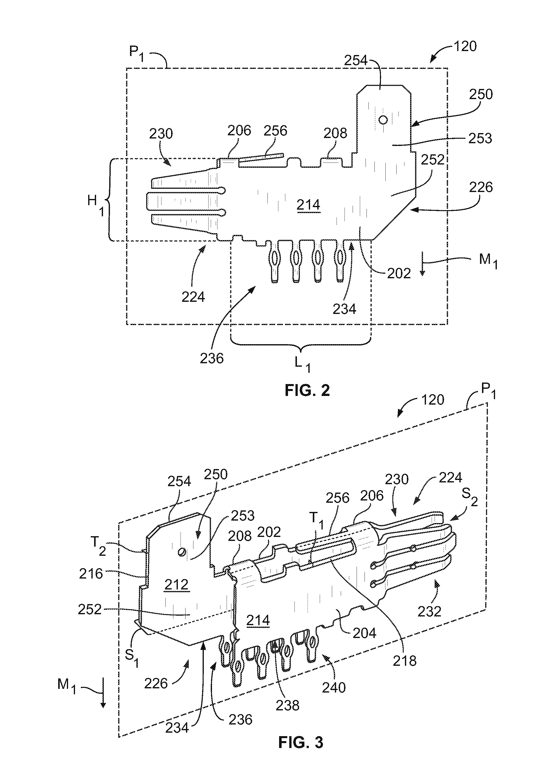
[0013]Embodiments described herein include power connectors that are configured to be mounted to a first electrical component, such as a circuit board. The power connectors include one or more power contacts that are capable of providing separate electrical pathways to deliver power to the first electrical component and to a separate second electrical component. For example, the power contacts may include board terminals that electrically engage a circuit board and a contact terminal that extends in a direction that is one of parallel to the circuit board or away from the circuit board. The contact terminal may engage the second electrical component (e.g., video card). In particular embodiments, power connectors may include first and second types of power contacts. The first type of power contacts include the contact terminals and are capable of delivering power to separate components, and the second type of power contacts may not include the contact terminals and may exclusively tr...


PUM


Abstract

Power connector including a connector housing having a mating side configured to engage an electrical connector. The connector housing also has a mounting side configured to interface with a circuit board. The connector housing includes a housing cavity that opens to the mating side. The power connector also includes a power contact that is held within the housing cavity. The power contact includes a body panel that extends along a contact plane and has board terminals and a contact terminal that extend from the body panel. The board terminals extend away from the body panel in a mounting direction to engage the circuit board. The contact terminal extends in a different direction that is one of parallel to the circuit board or away from the circuit board. The power contact is configured to transmit electrical power through the board terminals and through the contact terminal.

Description

BACKGROUND OF THE INVENTION[0001]The subject matter herein relates generally to power connectors, and more particularly, to power connectors configured to supply power to separate components in an electrical system.[0002]In some cases, it is desirable to reduce or minimize an amount of space that an electrical system or an electronic device uses. For example, a known computer system may include several electrical components that are enclosed within a common housing. To reduce the amount of spaced used by the computer system, the various electrical components may be arranged and configured with respect to one another to minimize the necessary space while also satisfying predetermined requirements for the computer system.[0003]It may also be desirable to increase the working capabilities of an existing electrical system, such as the computer system discussed above. For instance, during the lifetime of the computer system it may be necessary or desirable to replace an electrical compon...

Claims


Application Information

Patent Timeline
IPC IPC(8): H01R13/10
CPCH01R12/585H01R12/724H01R13/055Y10S439/907
Inventor ROITBERG, LEE JACOBO JOSE
Owner TYCO ELECTRONICS LOGISTICS AG (CH)
Learn More