Method for deblurring radar range-doppler images

a radar range and doppler technology, applied in the field of radar rangedoppler images, can solve the problems of large signal bandwidth, time resolution, and long signal duration, and achieve the effect of maximizing peak amplitud

Active Publication Date: 2011-10-25
LOCKHEED MARTIN CORP
View PDF30 Cites 50 Cited by
  • Summary
  • Abstract
  • Description
  • Claims
  • Application Information

AI Technical Summary

Benefits of technology

[0008]A method according to an aspect of the invention for deblurring a radar image. The method comprises the step of generating a return electromagnetic signal from one or more moving targets. A two-dimensional radar range-Doppler image is generated by matched linear filtering, where the matched linear filtering maximizes the peak amplitude of the combined set of pixels of the two-dimensional image. The filtering undesirably spreads the filtered pixels of the radar image in both range and Doppler frequency dimensions to thereby produce a point spread function. The method further comprises the step of coherently deblurring the radar image and its point spread functions by filtering with coefficients derived from a least-squares approximation of the blurred image to a desired image to thereby produce a deblurred image. In a preferred mode of this method, the least-squares criterion minimizes the difference (in both dimensions) between the two-dimensional image and the desired two-dimensional image.

Problems solved by technology

Time resolution of signals, such as, for example, radar signals, requires large signal bandwidth and fine Doppler resolution of such signals requires long signal duration.
For rotating objects, Doppler spreads of signals must be continually evaluated to provide clear radar images and, as a result, limitations are required on pulse train duration in order to return satisfactory images.
Radar signals are always accompanied by undesired noise.
Thus, a body having several different motions will have a “blurred” radar echo in which the targets and motions are not well resolved.

Method used


Image

  • Method for deblurring radar range-doppler images
  • Method for deblurring radar range-doppler images
  • Method for deblurring radar range-doppler images

Examples


Embodiment Construction

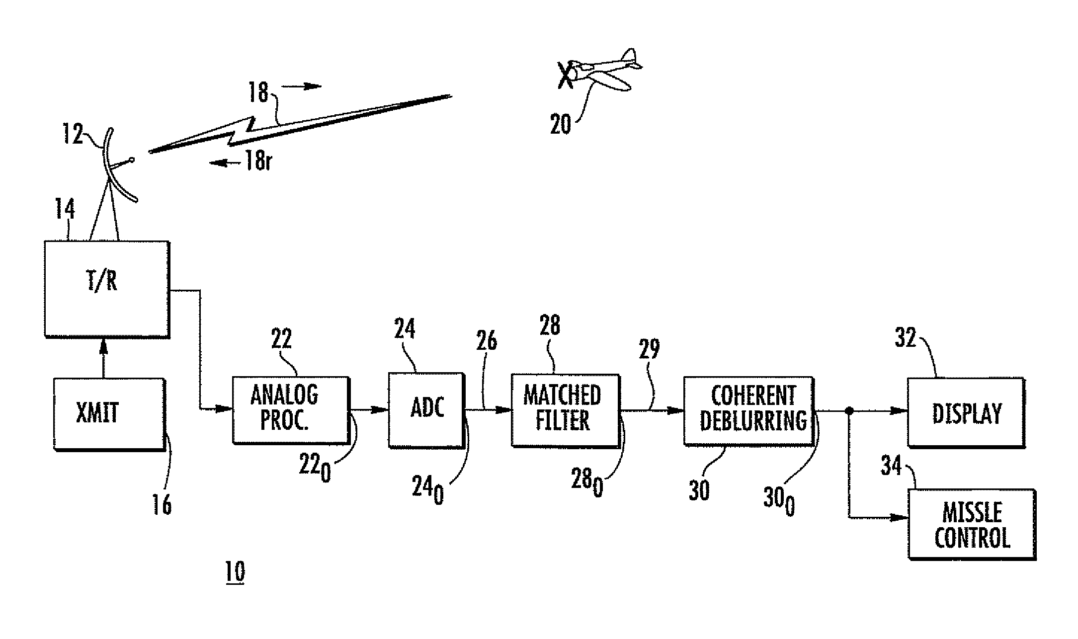
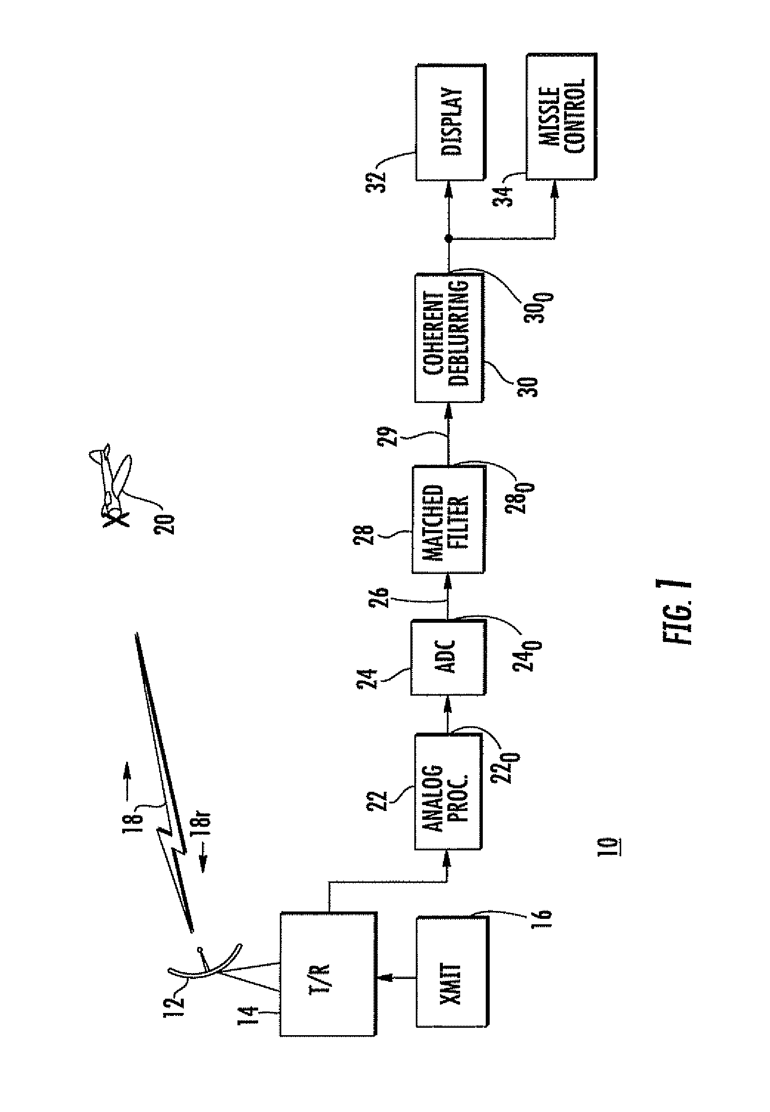
[0029]FIG. 1 is a simplified block diagram of a radar system 10 according to an aspect of the invention. In FIG. 1, radar system 10 includes an antenna 12 and transmit-receive (T / R) device 14. T / R device 14 receives signals to be transmitted from a transmitter (XMIT) 16, and couples the signals to be transmitted to antenna 12, which transmits the signals in the form of electromagnetic radiation, illustrated by a “lightning bolt” symbol 18. The electromagnetic radiation propagates outward, and impinges on a target, if present. An airborne target 20 is illustrated. The transmitted electromagnetic energy impinges on target 20, and a portion of the signal incident on the target is reflected back toward the radar antenna 12, as suggested by arrow 18r. The reflected electromagnetic signal is transduced by antenna 12, and coupled through the T / R device 14 to analog signal processing, illustrated by block 22. The analog signal processing may include low-noise amplification, and down convers...


PUM


Abstract

A method for displaying information relating to the range and Doppler of a remote target includes transmitting electromagnetic energy toward the target, and receiving reflected signals defining a two-dimensional (range-Doppler) radar image. The reflected signals are matched-filtered, which tends to blur the image. The image is deblurred while the features of thermal noise enhancement and irregularity of the deconvolved output are constrained to produce a single point deblurring output.

Description

[0001]This invention was made with Government support under contract number N00024-03-C-6110 awarded by the Department of the Navy. The Government has certain rights in this invention.FIELD OF THE INVENTION[0002]The present invention relates to radar range-Doppler images, and, more specifically, to a method for coherent deblurring of radar range-Doppler images.BACKGROUND[0003]The present invention relates to radar range-Doppler imaging. Time resolution of radar signals (which corresponds to range resolution) requires large signal bandwidth while fine Doppler resolution (which corresponds to range or “closing” rate or speed) requires long signal duration. This combination can be achieved in radar systems by continuously changing or “sweeping” the frequency of the transmitted electromagnetic signal. Such frequency sweeps may be linear with time (change frequency at a constant rate) or they may be nonlinear. One possible way to accomplish frequency sweeping is to transmit the electroma...

Claims


Application Information

Patent Timeline
Patent Type & Authority Patents(United States)
IPC IPC(8): G01S13/89G01S13/00G01S13/90
CPCG01S7/2923G01S13/582
Inventor URKOWITZ, HARRYCAMMERATA, JEFF D.
Owner LOCKHEED MARTIN CORP
Why Eureka
Try Eureka