Bonded metal fuselage and method for making the same

a fuselage and metal technology, applied in the field of fuselage structures of aerospace vehicles, can solve the problems of skin landing, increasing aircraft assembly time, etc., and achieve the effects of reducing weight, increasing strength, and reducing the number of fasteners

Active Publication Date: 2011-10-18
THE BOEING CO
View PDF24 Cites 16 Cited by
  • Summary
  • Abstract
  • Description
  • Claims
  • Application Information

AI Technical Summary

Benefits of technology

The disclosed embodiments provide a metal fuselage construction exhibiting reduced weight and / or increased strength. Through the use of bonded components, the number of fasteners may be reduced and thinner skins may be employed, particularly where fasteners are no longer required. The elimination of clips to structurally connect stringers and frames may reduce the load that may be transferred by the stringers to the frames, resulting in stringers and frames that may possess greater independent stability.

Problems solved by technology

The skin lands add weight to the aircraft, and increase aircraft assembly time since it is necessary to machine or otherwise remove a portion of the skin thickness in order to form the lands.

Method used


Image

  • Bonded metal fuselage and method for making the same
  • Bonded metal fuselage and method for making the same
  • Bonded metal fuselage and method for making the same

Examples


Embodiment Construction

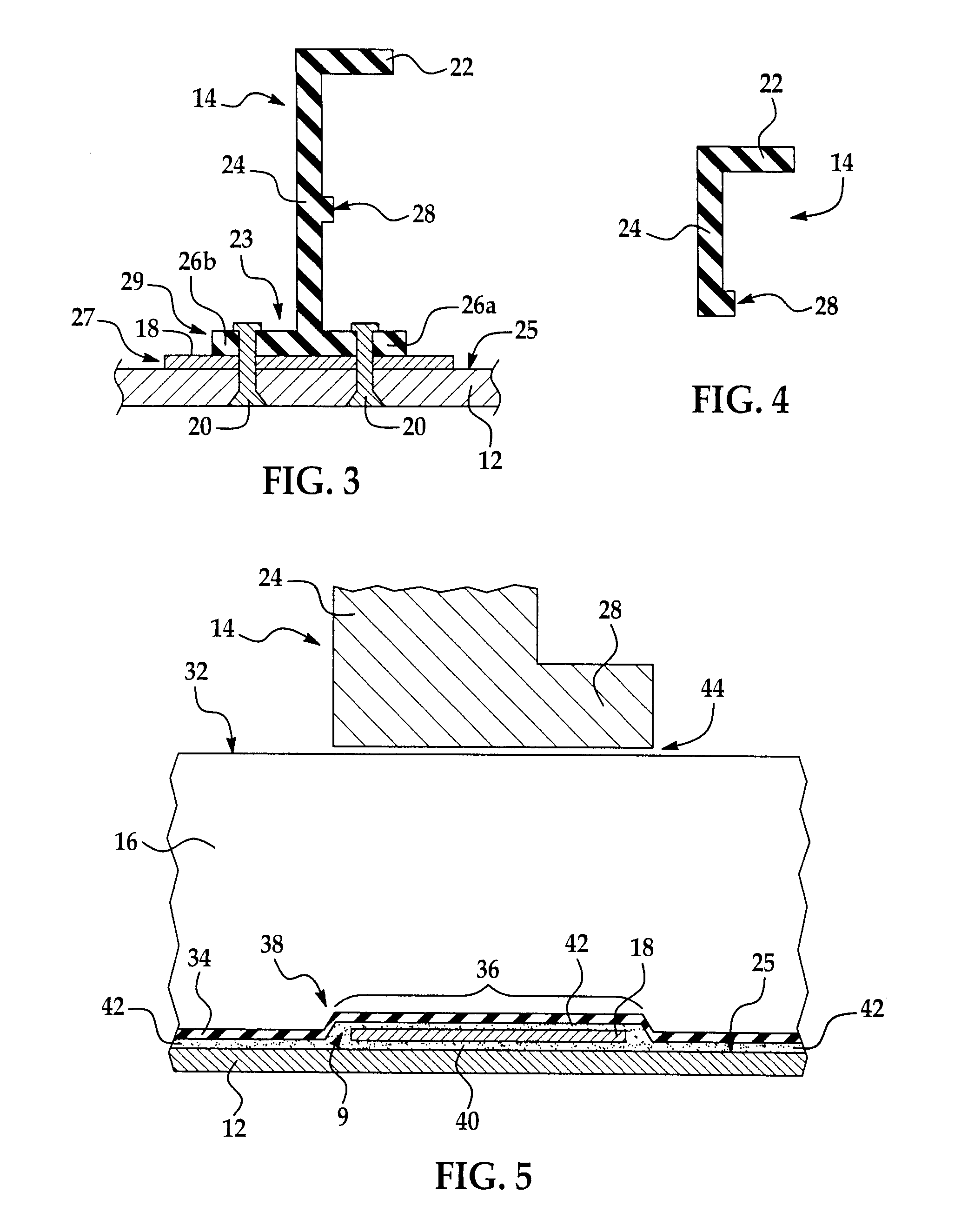
Referring first to FIGS. 1-5, a monocoque fuselage 10 for an aerospace vehicle such as an airplane, includes a longitudinal axis 15, and may possess any of various cross sectional shapes. In the illustrated embodiment, the fuselage 10 has a circular cross section, however other shapes are possible, including, without limitation, an oval or partial oval shape. The fuselage 10 broadly comprises an outer metal skin 12 formed of one or more sections, a plurality of barrel shaped, longitudinally spaced metal frames 14, and a plurality of circumferentially spaced, longitudinally extending stringers 16. The skin 12, frame 14 and stringers 16 may be formed from a suitable metal, such as, without limitation, aluminum or titanium.

Each of the frames 14 includes a single, inner flange 22 connected by a web 24 to an outer chord 23 defined by a pair of substantially coplanar outer flanges 26a, 26b which extend outwardly in opposite directions from the web 24. The web 24 may include a reinforcing ...


PUM


Abstract

A bonded metal fuselage for aerospace vehicles includes a monocoque structure having an outer metal skin, metal tear straps bonded to the outer skin and metal stringers bonded to the outer skin and to the tear straps. The outer chords of fuselage frames are fastened directly to tear straps and to the skin, obviating the need for clips to fasten the frames to the stringers.

Description

TECHNICAL FIELDThis disclosure generally relates to fuselage structures for aerospace vehicles, and deals more particularly with a fuselage having bonded metal components that result in increased fuselage strength and / or weight reduction.BACKGROUNDIn metal monocoque fuselage structures for aerospace vehicles such as airplanes, frames and stringers are commonly attached to the metal skin by fasteners such as rivets having heads that are countersunk within the skin. In some cases, circumferential strips of material, commonly known as “tear straps”, are placed between the skin and the frames in order to reduce hoop stress. Also, in some cases, separate clips are used to connect the stringers to the frames in order to transfer a portion of the load on the stringers to the frames. In order to assure that the skin exhibits uniform structural strength, the gauge or thickness of the skin in the area of the fasteners is increased so as to form “lands” or “pad-ups” whose thickness is sufficie...

Claims


Application Information

Patent Timeline
Patent Type & Authority Patents(United States)
IPC IPC(8): B64C1/00
CPCB64C1/068B64C1/12B64F5/0009B64F5/10
Inventor ANAST, PETER Z.HORST, PERRY T.
Owner THE BOEING CO
Why Eureka
Try Eureka