
Fuel economy improvement assist device and method of fuel economy improvement assist

a technology of fuel economy and assist device, which is applied in the direction of simultaneous indication of multiple variables, electrical control, machines/engines, etc., can solve the problems of reducing fuel economy, reducing fuel economy, and reducing fuel economy, so as to improve fuel economy and improve fuel economy. , the effect of improving fuel economy

Inactive Publication Date: 2011-10-18
TOYOTA JIDOSHA KK
View PDF10 Cites 15 Cited by
  • Summary
  • Abstract
  • Description
  • Claims
  • Application Information

AI Technical Summary

Benefits of technology

The device effectively alerts drivers to adjust their accelerator operation to reduce fuel consumption by providing clear feedback on the accelerator operation amount, leading to improved fuel efficiency and reduced fuel usage.

Problems solved by technology

On the other hand, the lamp is turned off when the actual operation is not suitable for improving fuel economy.
Thus, the displayed information may be insufficient.
Therefore, even drivers who keep fuel economy in mind, may frequently use the low accelerator operation amount region, and may possibly maintain for a long time an accelerator operation amount where the fuel economy is poor.
When the driver adjusts the accelerator depression in response to turning on and off of the lamp, the driver may frequently increase and decrease the accelerator depression around the threshold for turning on and off the lamp, which may reduce fuel economy.
However, it is not possible to provide appropriate accelerator operation instructions to the driver before the fuel economy is reduced.
However, according to the display device described in JP-A-2002-370560, the driver may not learn the way to avoid reducing fuel economy in response to the accelerator depression because the causes that lead to be reduced fuel economy are not displayed to the driver.

Method used


Image

  • Fuel economy improvement assist device and method of fuel economy improvement assist
  • Fuel economy improvement assist device and method of fuel economy improvement assist
  • Fuel economy improvement assist device and method of fuel economy improvement assist

Examples


example 1

1. Example 1

Display with Throttle Control in Accordance with Accelerator Pedal 13 Depression Speed Reflected

[0065]While the engine. ECU 14 preferentially executes engine control that maximizes the efficiency, the engine ECU 14 occasionally executes an engine control that increases the fuel consumption in order to secure the acceleration response and the moving performance in response to an operation of the accelerator pedal 13. FIG. 6 shows an example of an accelerator operation that increases fuel consumption. In FIG. 6, the solid lines indicate the accelerator operation amount and the throttle opening when the accelerator pedal 13 depression speed is above a predetermined value, while the dashed lines indicate those in the case where the accelerator pedal 13 depression speed is below the predetermined value.

[0066]For example, in the throttle control of gasoline cars, the engine ECU 14 detects the driver's intention to accelerate or climb up based on the accelerator pedal 13 depres...

example 2

2. Example 2

Displayed Value with Reduction in Efficiency Accompanied by Accelerator Depression Reflected

[0080]Automatic transmissions are designed to remain in the lock-up state whenever possible in order to improve efficiency. When the accelerator pedal 13 is suddenly depressed to increase the throttle opening, however, the lock-up clutch of the torque converter is released to obtain a high torque, which reduces the transmission efficiency of the engine.

[0081]FIG. 9 is a diagram for explaining the engine efficiency defined by the relationship between the engine speed and the torque. At approximately the same engine speed, for example, the efficiency is better as a higher torque is transmitted to the road surface. Thus, it is preferable to operate the accelerator pedal 13 so that the torque converter remains locked up as long as possible. If the accelerator pedal 13 depression speed is not so fast, the relationship between the engine speed and the torque changes as indicated by the ...

example 3

3. Example 3

Display Utilizing Overzone According to Accelerator Pedal 13 Depression Speed

[0096]The driver recognizes the overzone of the accelerator operation amount indicator 20 as a region where the fuel consumption increases abruptly. Therefore, the driver is expected to more effectively restrict the accelerator pedal 13 depression speed by more actively moving the displayed value to the overzone if the accelerator pedal depression speed is equal to or exceeds a predetermined value. Actively utilizing the overzone means increasing the displayed value to exceed the target value even if the accelerator operation amount is smaller than the target accelerator operation amount 14a, for example. The driver can recognize that the fuel consumption will increase when the accelerator pedal depression speed is too high because the displayed value is in the overzone even if the accelerator operation amount is not so large.

[0097]In order to display the displayed value for an accelerator opera...


PUM


Abstract

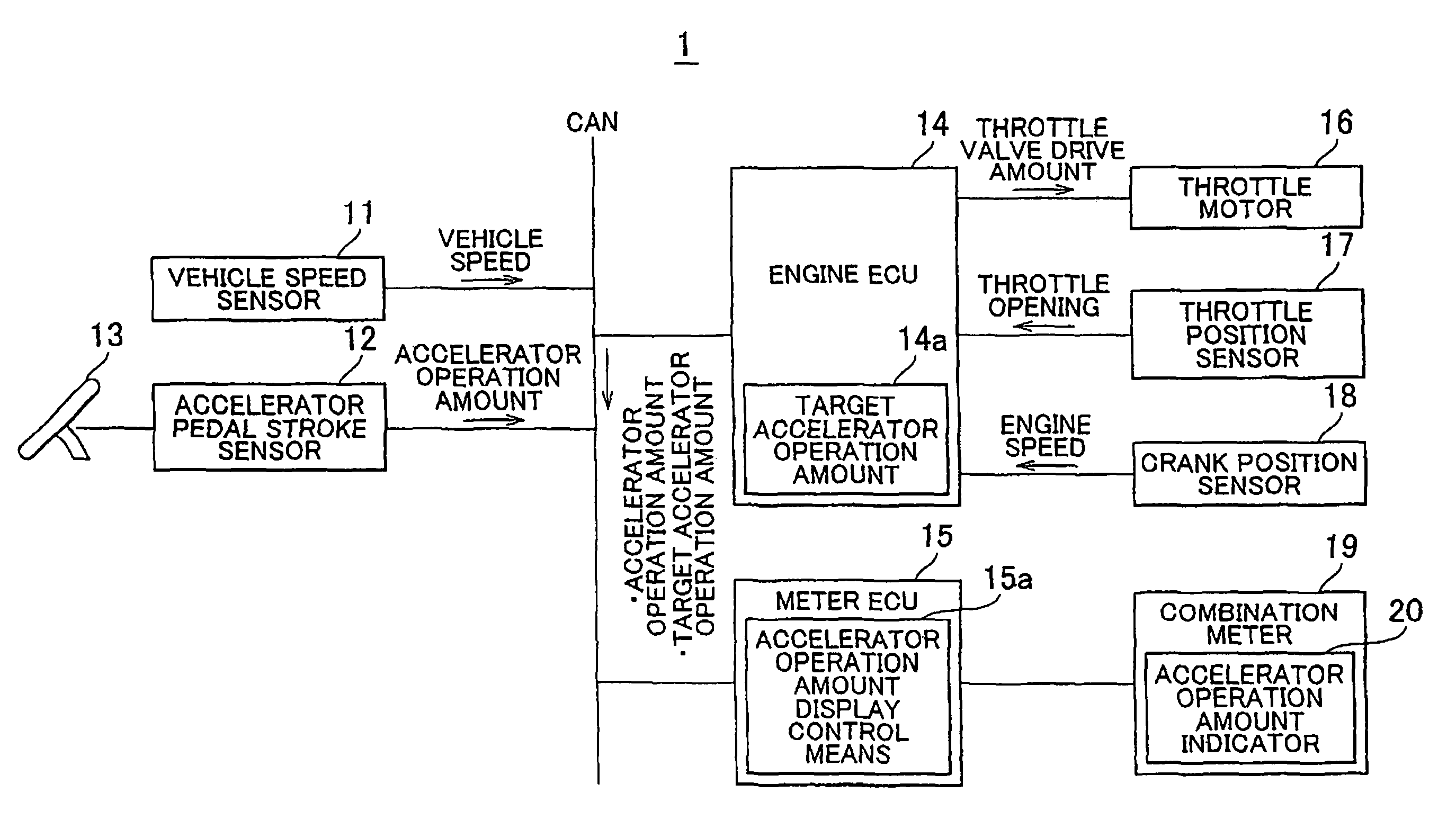
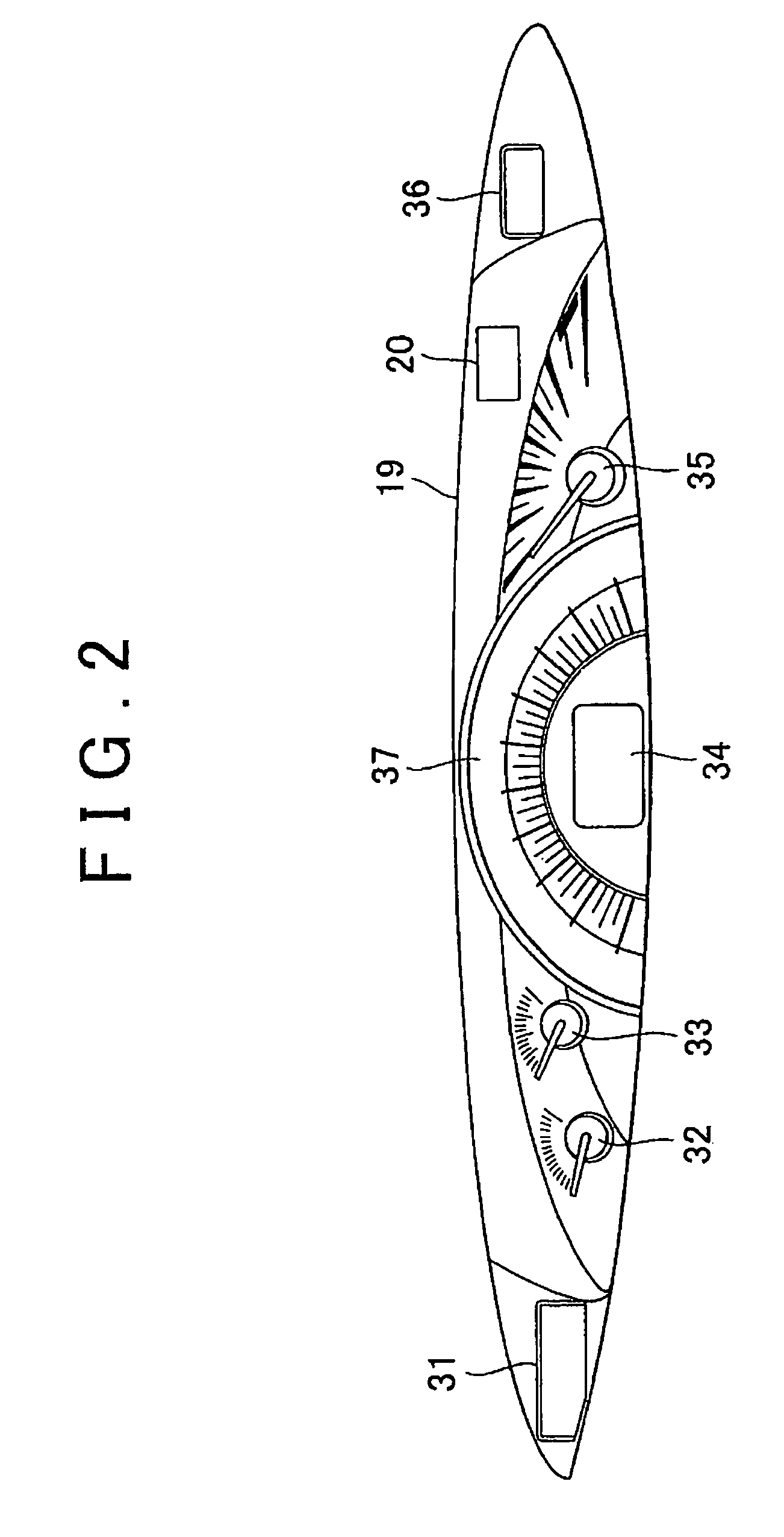
A fuel economy improvement assist device (1) has: accelerator operation amount detection means (12); and display control means (15a) for displaying, on a display device (20), a target value corresponding to a target accelerator operation amount and a deviation value of the detected accelerator operation amount from the target accelerator operation amount (14a). The display control means (15a) calculates an accelerator depression speed based on the detected accelerator operation amount, and variably displays the deviation value in accordance with the calculated accelerator depression speed.

Description

BACKGROUND OF THE INVENTION[0001]1. Field of the Invention[0002]The present invention relates to a fuel economy improvement assist device and a method of improving fuel economy by displaying the accelerator operation amount to a driver.[0003]2. Description of the Related Art[0004]In order to reduce the fuel consumption, various driving techniques such as avoiding sudden starting and acceleration, constant-speed driving, using higher gears, stopping engine idling are recommended. While many drivers keep the fuel economy in mind when driving, display devices that are used to display information to the drivers for improving fuel economy to further reduce the fuel consumption are known as below.[0005]Japanese Patent Application Publication No. 2003-220851 (hereinafter referred to as “JP-A-2003-220851”) describes a display device that it is determined whether the actual operation is suitable for improving fuel economy when the driver selected a gearshift mode for improving fuel economy, ...

Claims


Application Information

Patent Timeline
Patent Type & Authority Patents(United States)
IPC IPC(8): F02M51/00F02D41/00B60K35/00B60R16/02
CPCB60W50/14G01D7/04B60L2250/16F02D11/10F02D2041/228G01D2207/30
Inventor SAITO, KANKOMEDA, OSAMU
Owner TOYOTA JIDOSHA KK
Learn More