
Iron

a technology of iron and iron plate, applied in the field of iron, can solve the problems of increasing costs, and achieve the effects of improving the texture of iron, reducing costs, and improving blast strength

Active Publication Date: 2011-10-18
TSANN KUEN CHINA ENTERPRISE
View PDF5 Cites 2 Cited by
  • Summary
  • Abstract
  • Description
  • Claims
  • Application Information

AI Technical Summary

Benefits of technology

"The present invention provides an iron with a steam generating unit that can generate steam quickly and efficiently in a limited space. The iron has a blast unit for rapid steam blasting, a steam spraying unit for spraying steam onto the iron, and a main spraying unit and blast spraying unit for different textures and appearances. The water enters the blast unit and is quickly steamed and pushed forward, resulting in a high-intensity blast. The small electric tray and big electric tray can be separately mounted, allowing for different materials or paint to improve appearance. The iron also has a twist passage for improved blast strength and a carrying mechanism for water to the blast outlet. Overall, the invention provides an improved and cost-effective solution for blasting with a high-quality steam iron."

Problems solved by technology

Because the steam generating unit has large space, the blast force from the outlet is often inadequate, and a big heating plate must be used to generate enough blast force, increasing cost.

Method used


Image

  • Iron
  • Iron

Examples


Embodiment Construction

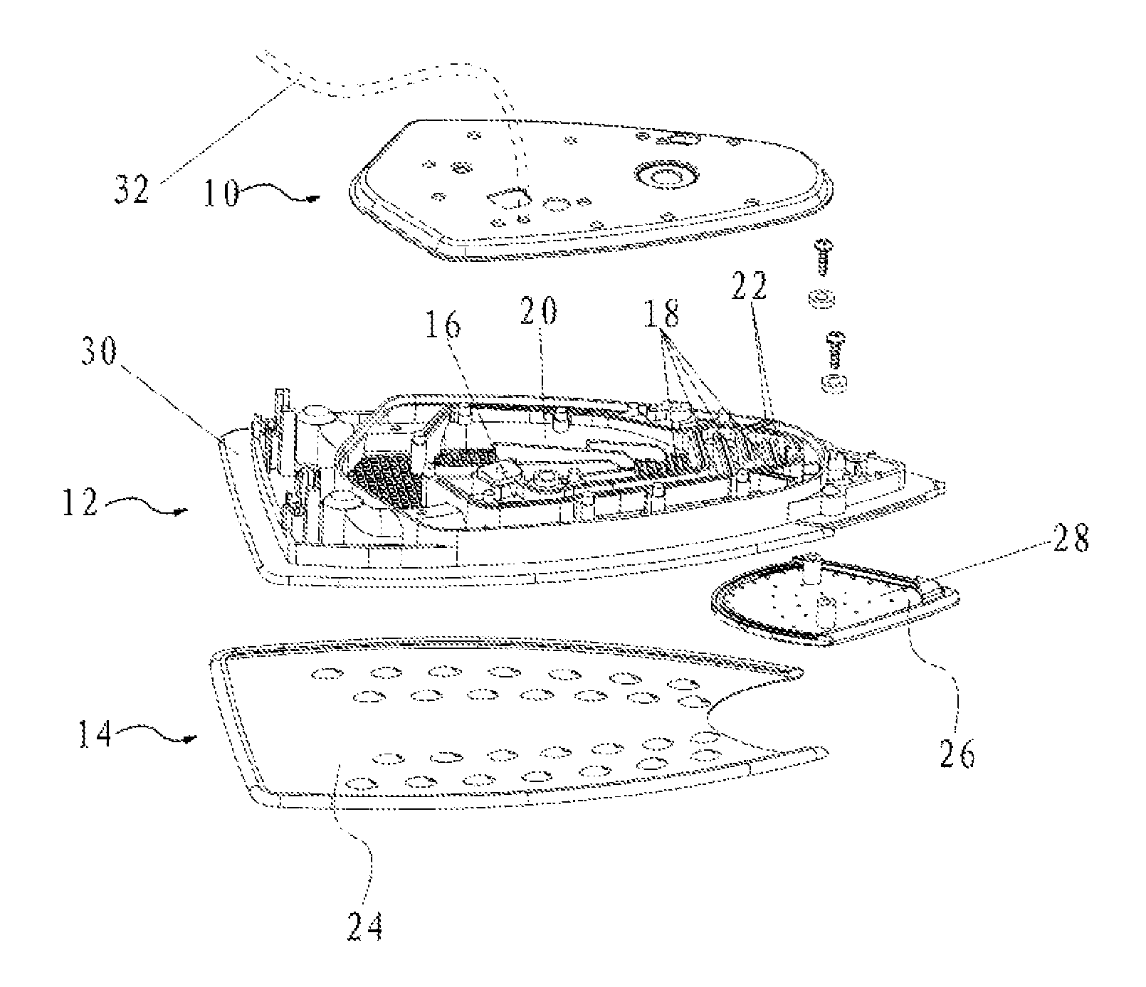
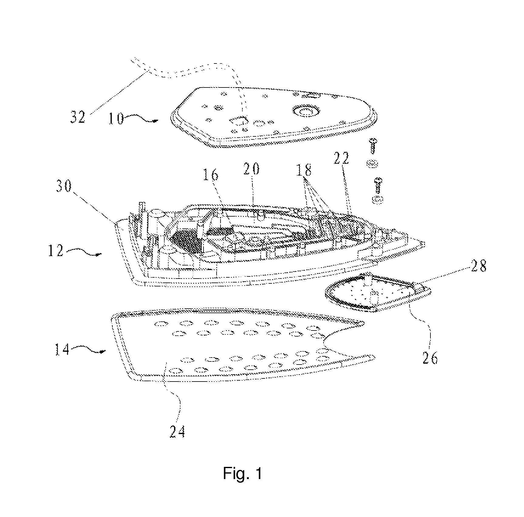
[0016]Referring to FIG. 1, it is an exploded view of the upper shell, lower shell and the steam spraying unit of the iron of the present invention. An iron comprises a water tank, an upper shell 10, a lower shell 12 and a steam spraying unit 14.

[0017]Referring to FIG. 1, the upper shell 10 and the lower shell 12 connected to form a separated blast cavity and a steam generating cavity. The blast cavity has a small electric tray 28 for providing heating for the blast cavity, the blast cavity and the small electric tray 28 cooperated to be the blast unit. The steam generating cavity has a main electric tray 30 for providing heating for the steam generating cavity, the steam generating cavity and the main electric tray 30 cooperated to be the steam generating unit.

[0018]Referring to FIG. 1, the blast cavity comprising a blast dripping point 16 and a blast flow passage 18, the blast flow passage 18 is a twist passage. The blast flow passage is connected to the blast dripping point 16, an...


PUM


Abstract

An iron comprising a water tank, a blast unit, a steam generating unit and a steam spraying unit. The blast unit has a first inlet and a first outlet, the first inlet is connected to the inlet-pipe of the inlet of the water tank, wherein the blast unit generates steam rapidly in a limited space. The steam generating unit has a second inlet and a second outlet, the second inlet being connected to the inlet-pipe of the inlet of the water tank, wherein the steam generating unit heats the water to generate steam. The steam spraying unit connects the first and second outlet, has plural steam apertures, and sprays steam. Because a blast unit is arranged for the rapid steam generation in a limited space, the iron of the present invention obviates the disadvantages in the existing irons and improves steam blast strength, intensity at a low cost.

Description

FIELD OF THE INVENTION[0001]The present invention relates to an iron.BACKGROUND OF THE INVENTION[0002]Irons existing currently in the market usually comprise a water tank, a steam generating unit and a steam spraying unit. The steam generating unit has an inlet and an outlet, wherein the inlet connected to the inlet-pipe of the water tank, the outlet connected to the steam spraying unit, wherein the steam generating unit used for heating the water to generate steam. The steam spraying unit has plural apertures, and the steam spraying unit is used for spraying steam to iron. Because the steam generating unit has large space, the blast force from the outlet is often inadequate, and a big heating plate must be used to generate enough blast force, increasing cost.SUMMARY OF THE INVENTION[0003]The object of the present invention is to provide an iron which obviates the disadvantages of conventional irons that the steam generating unit has large space thus the blast force from the outlet ...

Claims


Application Information

Patent Timeline
Patent Type & Authority Patents(United States)
IPC IPC(8): D06F75/20D06F75/38
CPCD06F75/18D06F75/14D06F75/20D06F75/38
Inventor PAN, CHIENCHIHJIANG, YAN
Owner TSANN KUEN CHINA ENTERPRISE
Learn More