
Stepping motor with a coded pole pattern

a technology of stepping motors and pole patterns, applied in the direction of magnetic bodies, dynamo-electric converter control, magnetic circuit shapes/forms/construction, etc., can solve problems such as pattern formation and significant ambiguity in the position of rotors

Inactive Publication Date: 2011-10-11
CORRELATED MAGNETICS RES LLC
View PDF49 Cites 11 Cited by
  • Summary
  • Abstract
  • Description
  • Claims
  • Application Information

AI Technical Summary

Problems solved by technology

The repeating pattern gives rise to significant ambiguity in the position of the rotor for any given drive signal configuration.

Method used


Image

  • Stepping motor with a coded pole pattern
  • Stepping motor with a coded pole pattern
  • Stepping motor with a coded pole pattern

Examples


Embodiment Construction

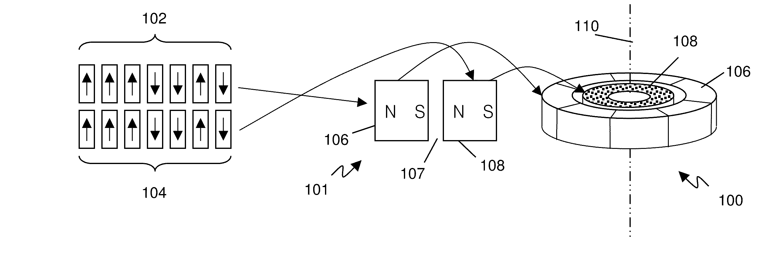
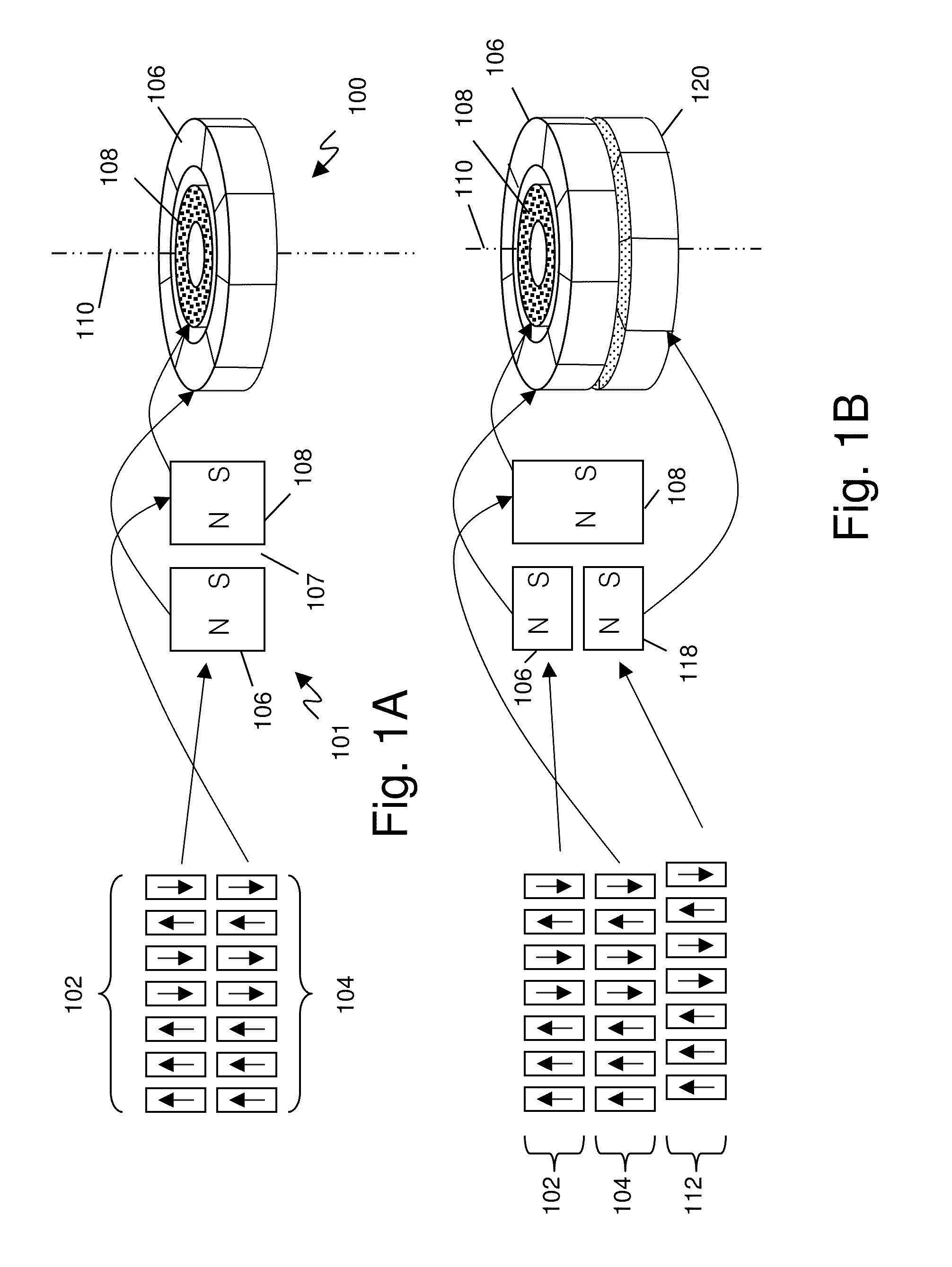
[0050]FIG. 1A depicts an exemplary single phase stepping motor in accordance with the present invention. Referring to FIG. 1A, FIG. 1A shows a stepping motor 100 having a rotor 108 and stator 106. The rotor and stator each have seven magnets radially magnetized with poles facing one another across the rotor / stator gap. A vertical cross section 101 shows the relative pole orientation of the stator 106 and rotor 108 across the rotor / stator gap 107. FIG. 1A shows a stator (outer ring) magnetic pole field pattern 102 and a rotor (inner ring) magnetic field pattern 104. The patterns are shown linearly for simplicity, but actually represent the rotational sequence of magnets in the motor 100. Typically, the rotor is permanently magnetized and the stator comprises electromagnets that may be driven to generate torque or motion, as desired, in the rotor. The stator field pattern is shown using the same code as the rotor and in the same position as the rotor, thus, holding the rotor in a stab...


PUM


Abstract

The present invention relates to a stepping motor with a magnet pole pattern having a predetermined pattern around the circumference of the stepping motor. In one embodiment, the pattern relates to a code having a unique single maximum autocorrelation peak over the period of the code. Example codes include Barker codes, PN codes, Kasami codes, Golomb ruler codes, and other codes. In one embodiment, the rotor and stator have a matching pole pattern. In one embodiment, the drive is arranged to align the poles in an inline configuration, alternatively, the drive may be arranged to align the poles in a diagonal configuration. In a further embodiment, one or more sets of poles are provided on the stator, each set being offset rotationally by a partial pole spacing.

Description

RELATED APPLICATIONS[0001]This Non-provisional Application claims the benefit under 35 USC 119(e) of prior provisional application 61 / 247,931 titled “Stepping Motor With Coded Pole Pattern” filed Oct. 1, 2009 by Fullerton et al; this Non-provisional application is a continuation-in-part of non-provisional application Ser. No. 12 / 478,911, titled “Magnetically Attachable and Detachable Panel System,” filed Jun. 5, 2009 by Fullerton et al., now published as US2009 / 0250574-A1, which is a continuation in part of non-provisional application Ser. No. 12 / 476,952 filed Jun. 2, 2009, by Fullerton et al., titled “A Field Emission System and Method”, which is a continuation-in-part of Non-provisional application Ser. No. 12 / 322,561, filed Feb. 4, 2009 by Fullerton et al., titled “System and Method for Producing an Electric Pulse”, which is a continuation-in-part application of Non-provisional application Ser. No. 12 / 358,423, filed Jan. 23, 2009 by Fullerton et al., titled “A Field Emission Syst...

Claims


Application Information

Patent Timeline
Patent Type & Authority Patents(United States)
IPC IPC(8): H02K37/00
CPCG09F7/04H02K1/27H02K29/00
Inventor FULLERTON, LARRY W.ROBERTS, MARKRICHARDS, JAMES LEE
Owner CORRELATED MAGNETICS RES LLC
Learn More