Patch cable physical link identification device

a physical link identification and patch cable technology, applied in the direction of electrical discharge lamps, substation equipment, coupling device connections, etc., can solve the problems of difficult to differentiate between the groups of cables within one category, difficult management of network closets where connecting cabling generally converges, and inability to be permanen

Active Publication Date: 2011-10-11
LINK LIGHT TECH
View PDF8 Cites 11 Cited by
  • Summary
  • Abstract
  • Description
  • Claims
  • Application Information

AI Technical Summary

Benefits of technology

[0023]The device utilizes a single unused pair of wires connected to a typical RJ-45 ethernet plug to carry DC voltage from a small long life battery integrated into a first modular plug, sending such voltage when activated through a switch to a light emitting diode molded within the modular plug located at the opposite end of the same patch cord. When a switch is pushed on the first connector, voltage is passed through one pair of the category wiring facilitating an isolated positive and negative DC connection to the light emitting diode end of the cable, thereby illuminating the LED and providing an immediate indication of the exact termination point of a given patch cord being tested.
[0024]Diodes are inserted between the positive flow of current and the RJ plug protecting both the circuit from a terminal condition as well as the device to which the network port is connected from a potentially harmful voltage condition. The insertion of a diode provides an isolated, closed loop circuit for the operation of the lamp. By allowing illumination of the opposite end of a given patch cord without removing the patch cord from service, the corresponding end of a given patch cord can be identified even as the cord remains in service.
[0025]The operation of the invention allows a network administrator or wiring technician to reconfigure cabling utilizing the invention without the need to physically retrace the topography or configuration of the patch cord, or to disconnect the patch cords to apply testing equipment to determine whether a particular modular plug is actually terminated with an identified opposite end of the same cable. Additionally, a technician may install an unlimited number of cables simultaneously without having to “map” each connection. A bundle of perhaps one hundred cables may be put into place through the cable management devices and upon connection to the patch panel, individual cable may be identified with the push of a button and subsequently connected to their desired device. In such a scenario, five to ten such cables may typically be correctly identified using the invention and connected in the time it takes to log a single patch connection without the invention.

Problems solved by technology

Networking closets where connecting cabling generally converges can be difficult to manage in middle to large scale installations where there may be dozens, and perhaps hundreds of cable converging in a closet where patch panels are utilized to allow flexibility in connections and reconfiguration of the networking layout.
Even if various colors are used to designate the difference between telephone cabling, computer network cabling or video cabling, it is still difficult to differentiate between the groups of cable within one category.
Connections are not permanent and they often need to be moved between various devices on demand or to reconfigure the data processing network or telephone system being used.
This is repeated hundreds of times and this conventional effort at keeping track of the topography or configuration of the physical wiring in a given building becomes a problem.
Not only is it time consuming, it's sometimes inaccurate, and it is not always a permanent reference.
Also, under normal circumstances, if the log gets lost, or the writer makes a mistake, or if any changes are made in the wiring closet that are not documented (a common situation), one must start the entire process over.
Such a process also does not account for the addition of new devices to the network closet or to the device or equipment rack contained therein, additional premise wiring being installed and needing to be patched into the system, individual patch cabling replacement due to upgrade or failure (which would need to be completed one cable at a time to maintain or create a log), or a network device being removed.
This is time consuming in itself, and labels fall off, are difficult to find within a thick bundle of cables, and otherwise are occasionally misread if they are reviewed upside-down and must be addressed on a one by one basis.
This is and has been a time consuming task for many wiring technicians and network administrators.

Method used


Image

  • Patch cable physical link identification device
  • Patch cable physical link identification device
  • Patch cable physical link identification device

Examples


Embodiment Construction

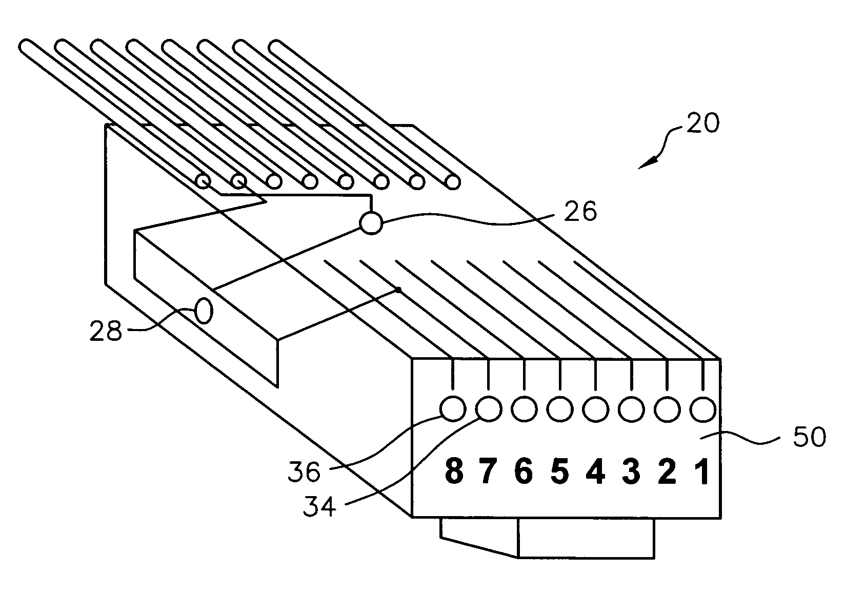
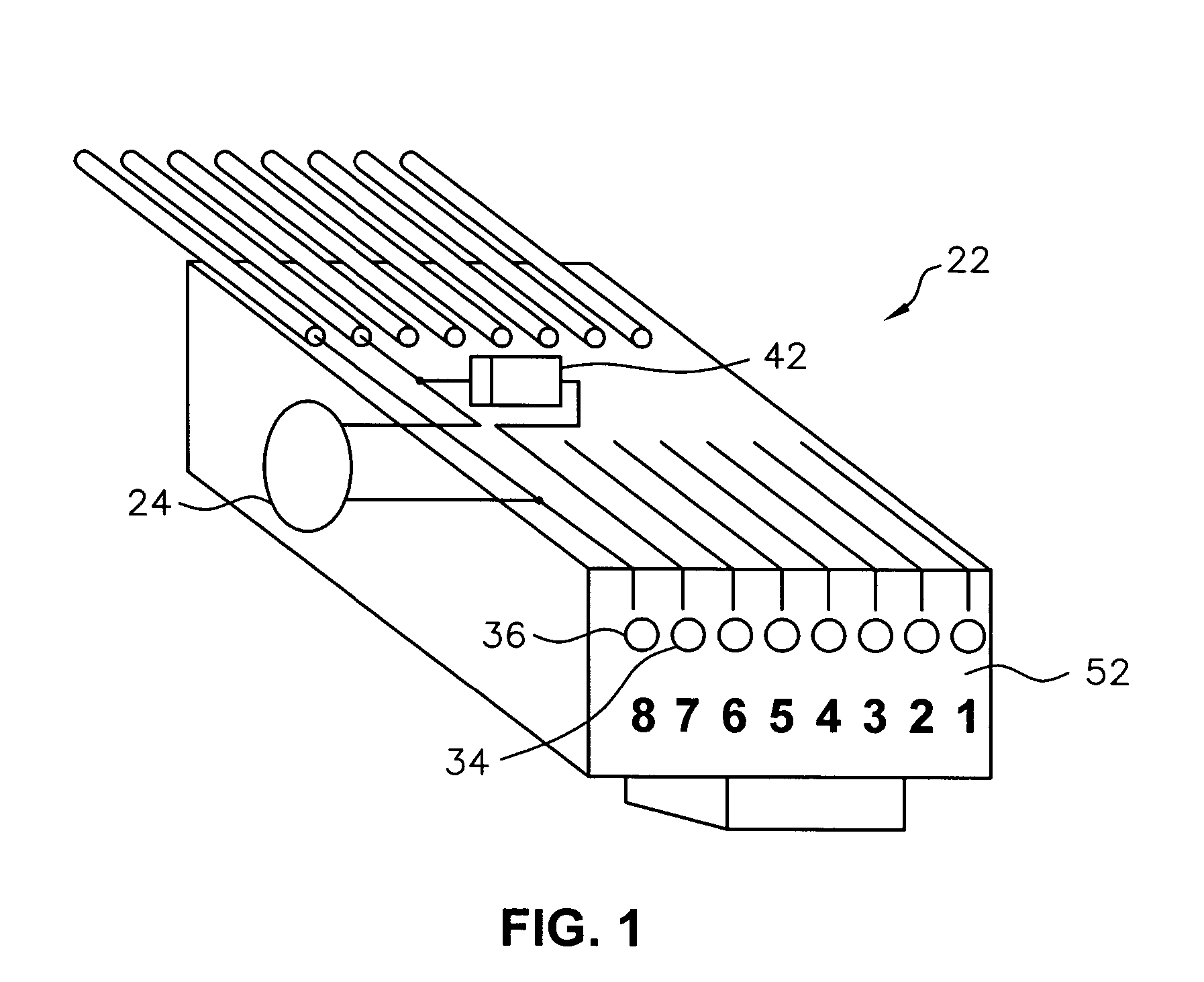
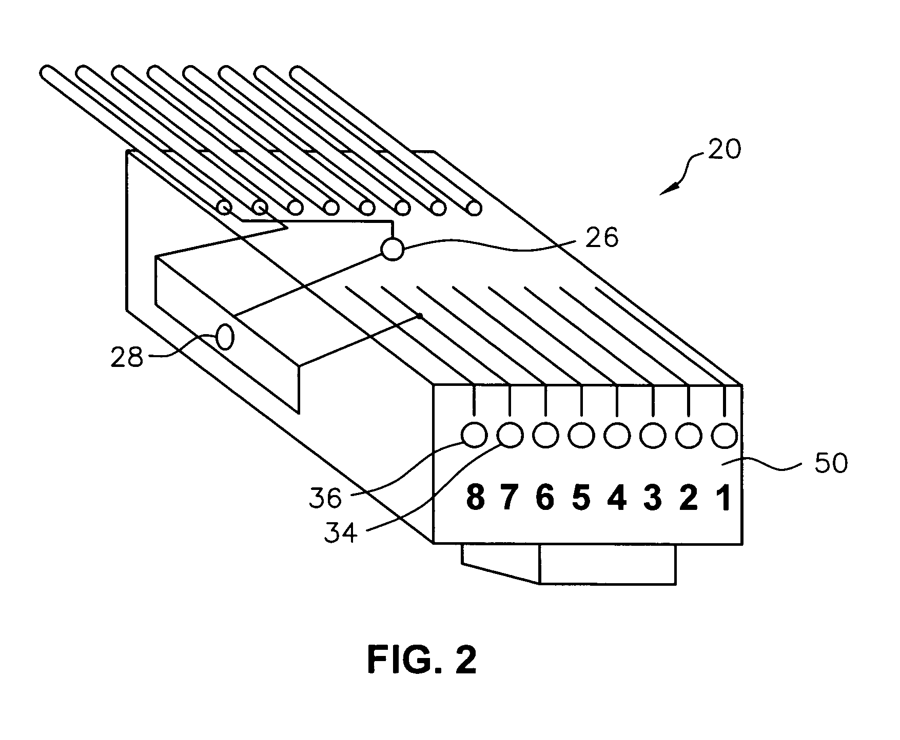
[0031]And now the invention shall be described in terms of the preferred embodiment utilizing various figures provided wherein like-numbers refer to like-parts. The invention may be applied in two different, but generally similar embodiments depending on the application and convenience desired in the use of the cables to which the inventions are applied. FIGS. 1 and 2 present the internal configuration of a complimentary pair of RJ45 type modular connectors which are used in the first embodiment of the invention where complete compatibility to the power over ethernet protocol remains available where a user may desire to apply the invention in such an environment.

[0032]FIG. 3 is a schematic diagram illustrating the typical configuration of a telecommunications interconnect cable for data or voice devices which contain a visual identification component for the purposes of identification of the opposite end of the termination of a given individual cable. For purposes of clarity, it sho...


PUM


Abstract

A system for locating corresponding ends of a communications or data patch cable used to conduct a signal between computing or telecommunications devices. The invention provides a physical indication of the location of an opposite end of a given patch cable when a switching means on the first end of the same cable is activated. The invention utilizes an existing pair of wires in category-type cables to send a DC voltage when activated to illuminate a light emitting diode in the opposite end of a patch cable thereby providing an immediate indication of the location of the termination of the opposite end of a patch cable making it possible to visually identify a cable without removing the cable from service or from connection of the modular plugs on either end of the cable.

Description

CROSS REFERENCES TO RELATED APPLICATIONS[0001]This application claims the benefit of the applicant's provisional application Ser. No. 60 / 522,195 which was filed Aug. 30, 2004 and assigned to the assignee of the present application.BACKGROUND OF THE INVENTION[0002]1. Field of the Invention[0003]The present invention relates to communications and data processing patch cords and cables used in telephone systems, computer networking systems including ethernet connections, and for other electronic cabling systems.[0004]2. Description of the Related Art[0005]Communications and computer networking systems generally utilize cabling complying with certain standards such as ethernet or other related cabling standard protocols. Many buildings utilize networking cable which conforms to an ethernet standard utilizing what is commonly known as Category 5 (“Cat 5”) Wire standards or higher. Telephone systems such as electronic telephone switches and private branch exchanges may utilize similar cab...

Claims


Application Information

Patent Timeline
Patent Type & Authority Patents(United States)
IPC IPC(8): H01R9/22
CPCH01R13/465
Inventor ANKERSTJERNE, WILLIAM D.
Owner LINK LIGHT TECH
Why Eureka
Try Eureka