
Method, apparatus and computer program product for monitoring data transmission connections

a data transmission connection and computer program technology, applied in the field of method, apparatus and computer program product for monitoring data transmission connection, can solve the problems of difficult monitoring of the lub interface of the 3g, failure of monitoring calls using the method, and inability to work in all mobile networks, so as to facilitate the implementation of the invention and facilitate the operation of call tracing

Active Publication Date: 2011-10-04
EXFO
View PDF30 Cites 132 Cited by
  • Summary
  • Abstract
  • Description
  • Claims
  • Application Information

AI Technical Summary

Benefits of technology

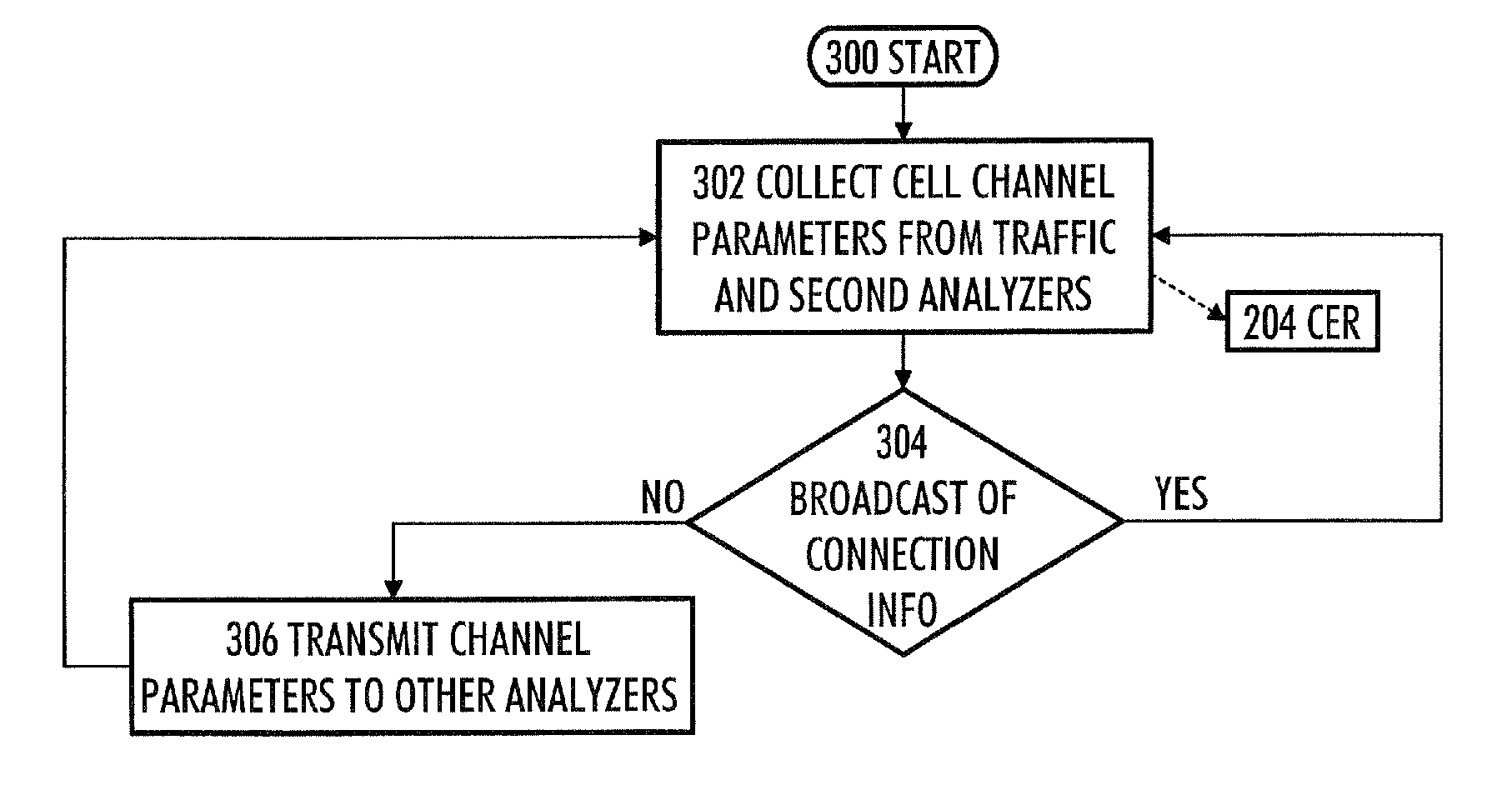
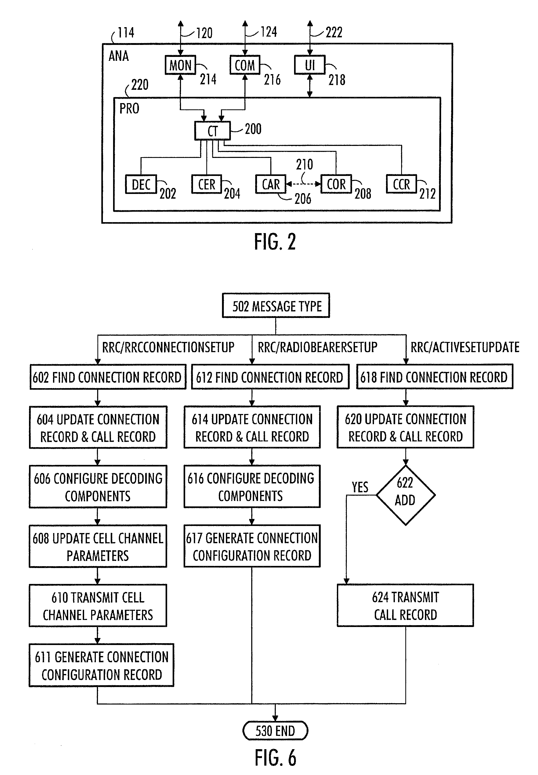
The invention provides an improved method for monitoring data transmission connections between a cellular radio network and a subscriber terminal with two analyzers. The method involves collecting connection information on each data transmission connection using two analyzers, transferring the information to the other analyzer, and using it in combination with the first analyzer's information for analyzing the second data transmission connection. This allows for more efficient monitoring of data transmission connections and easy call tracing. The invention can be used for monitoring various types of cellular radio networks and can be implemented easily.

Problems solved by technology

The described method does not function in all mobile networks, because there are not always common parameter values, in which case monitoring handovers with the method fails, and thus monitoring calls by using the method fails too.
It is difficult to monitor the lub interface of a 3G cellular radio network because monitoring protocols used on AAL2 (ATM Adaptation Layer Type 2) connections requires capturing the configuration information of the protocols from the configuration messages transmitted to a mobile phone and from the configuration messages transmitted to a base transceiver station.
If the interface monitoring is distributed between two devices and the handover takes place between the devices, the receiving apparatus has no information on configuration messages of the subscriber terminal, so that decoding of protocols cannot be performed.
However, this takes processor time and can lead to incorrect decoding results.
In addition, it is not necessarily possible to specify the signaling of which subscriber terminal is monitored, and so the call tracing fails.
Automatic identification of protocols may also be needed because it is not always possible to monitor the signaling transaction from the beginning.
Thus, the connections that are not monitored from the beginning cannot be configured with configuration based merely on monitoring messages.
This is problematic, however, because different interfaces can be positioned far away from each other (e.g. in a case of Abis / lub interfaces), whereby the problem is the transfer of messages from the interfaces to the device to be monitored; the problem is also that the performance of one device is not necessarily sufficient for monitoring all cells.
So in a case where the start of a call is monitored with a first analyzer and where the call is transferred with handover to an interface monitored by a second analyzer, the call cannot be identified on the second interface, and thus call tracing cannot be performed.
In call tracing, the problem is both the configuration of the connections to be monitored and the monitoring of handovers.

Method used


Image

  • Method, apparatus and computer program product for monitoring data transmission connections
  • Method, apparatus and computer program product for monitoring data transmission connections
  • Method, apparatus and computer program product for monitoring data transmission connections

Examples


Embodiment Construction

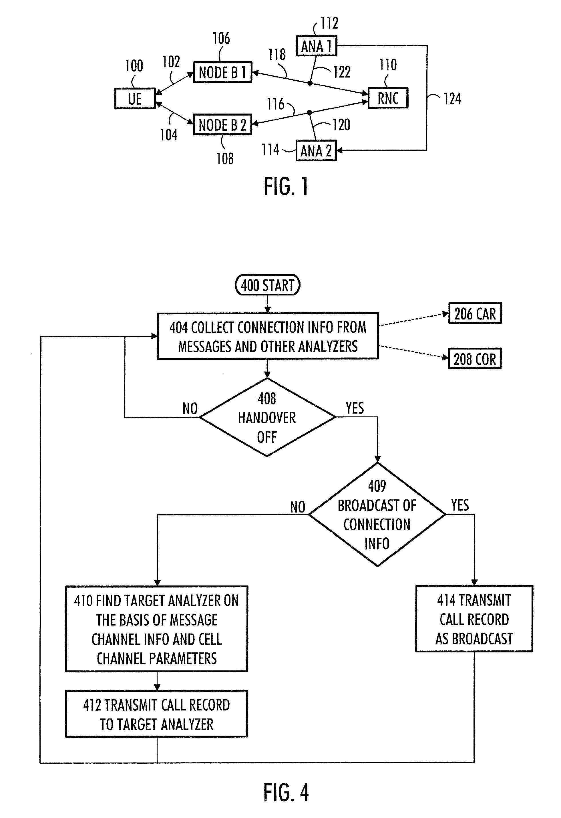
[0027]FIG. 1 shows an example of a cellular radio network to which monitoring can be applied. The cellular radio network may be based on, for example, GSM (Global System for Mobile Communications), WCDMA (Wideband Code Division Multiple Access) or CDMA (Code Division Multiple Access) technology. Here, only a radio network controller 110 and two base transceiver stations 106, 108 under its control are described. A subscriber terminal 100 has a radio connection 102 to the first base transceiver station 106, and a radio connection 104 to the second base transceiver station 108.

[0028]It is obvious that the cellular radio network also comprises other devices, but it is not relevant to describe them here. Depending on the system, the names of the devices may vary; therefore, the radio network controller 110 can also be called a base station controller, the base transceiver station 106, 108 can be called node B, and the subscriber terminal 100 can be called user equipment.

[0029]There is a ...


PUM


Abstract

A method, device and computer program product for monitoring data transmission connections. The method comprises monitoring data transmission connections between a cellular radio network and a subscriber terminal with two analyzers. With the first analyzer, first connection information is collected on a first data transmission connection of the subscriber terminal to a first cell. With the second analyzer, second connection information is collected on a second data transmission connection of the subscriber terminal to a second cell. The first connection information is transferred from the first analyzer to the second analyzer. In the second analyzer, the first connection information is used combined with the second connection information for analyzing the second data transmission connection.

Description

FIELD[0001]The invention relates to a method for monitoring data transmission connections between a cellular radio network and a subscriber terminal with two analyzers; an analyzer for monitoring data transmission connections between a cellular radio network and a subscriber terminal; and a computer program product encoding a computer process for monitoring data transmission connections between a cellular radio network and a subscriber terminal.BACKGROUND[0002]In digital data transmission networks, such as in cellular radio networks, different analyzers and simulators for measuring the operation of the network are used. Analyzers can be used for monitoring data transmission connections between a cellular radio network and a subscriber terminal, for example.[0003]Publication U.S. Pat. No. 5,884,175 discloses a method and an apparatus for monitoring data transmission transactions in a mobile network. The method of the publication comprises monitoring a first signaling channel, and det...

Claims


Application Information

Patent Timeline
Patent Type & Authority Patents(United States)
IPC IPC(8): H04B7/00H04W4/00H04W24/00H04W24/08H04W36/08
CPCH04W24/08
Inventor IKAHEIMO, JORMA
Owner EXFO
Learn More