
Device for the injection of a solid or semi-solid implant

a solid or semi-solid technology, applied in the field of injection devices, can solve the problem of limited space requirements of injection devices, and achieve the effect of preventing any risk of accidental injury that could contaminate the practitioner

Active Publication Date: 2011-10-04
IPSEN PHARMA SAS
View PDF48 Cites 22 Cited by
  • Summary
  • Abstract
  • Description
  • Claims
  • Application Information

AI Technical Summary

Benefits of technology

Owing to these features, the present invention provides a device for injecting an implant including a limited number of parts, and is thus less expensive to manufacture and simpler to assemble. Moreover, the configuration of the injection device is the same before and after use, the main body moving away from the proximal position towards a distal position, then returning to the initial proximal position, such that the space requirement of the injection device is limited, which facilitates packaging and storage of such devices.
Owing to this other feature, the relative movements of the constituent parts of the injection device in relation to each other are simplified, which avoids the risk of the device malfunctioning.
Thus, prior to use, it is not possible to lock the injection device inadvertently, whereas after use, the secondary body is irreversibly locked on the main body, which makes any subsequent use of the injection device according to the invention impossible. Moreover, any risk of accidental injury that could contaminate the practitioner is prevented.

Problems solved by technology

Moreover, the configuration of the injection device is the same before and after use, the main body moving away from the proximal position towards a distal position, then returning to the initial proximal position, such that the space requirement of the injection device is limited, which facilitates packaging and storage of such devices.

Method used


Image

  • Device for the injection of a solid or semi-solid implant
  • Device for the injection of a solid or semi-solid implant
  • Device for the injection of a solid or semi-solid implant

Examples


first embodiment

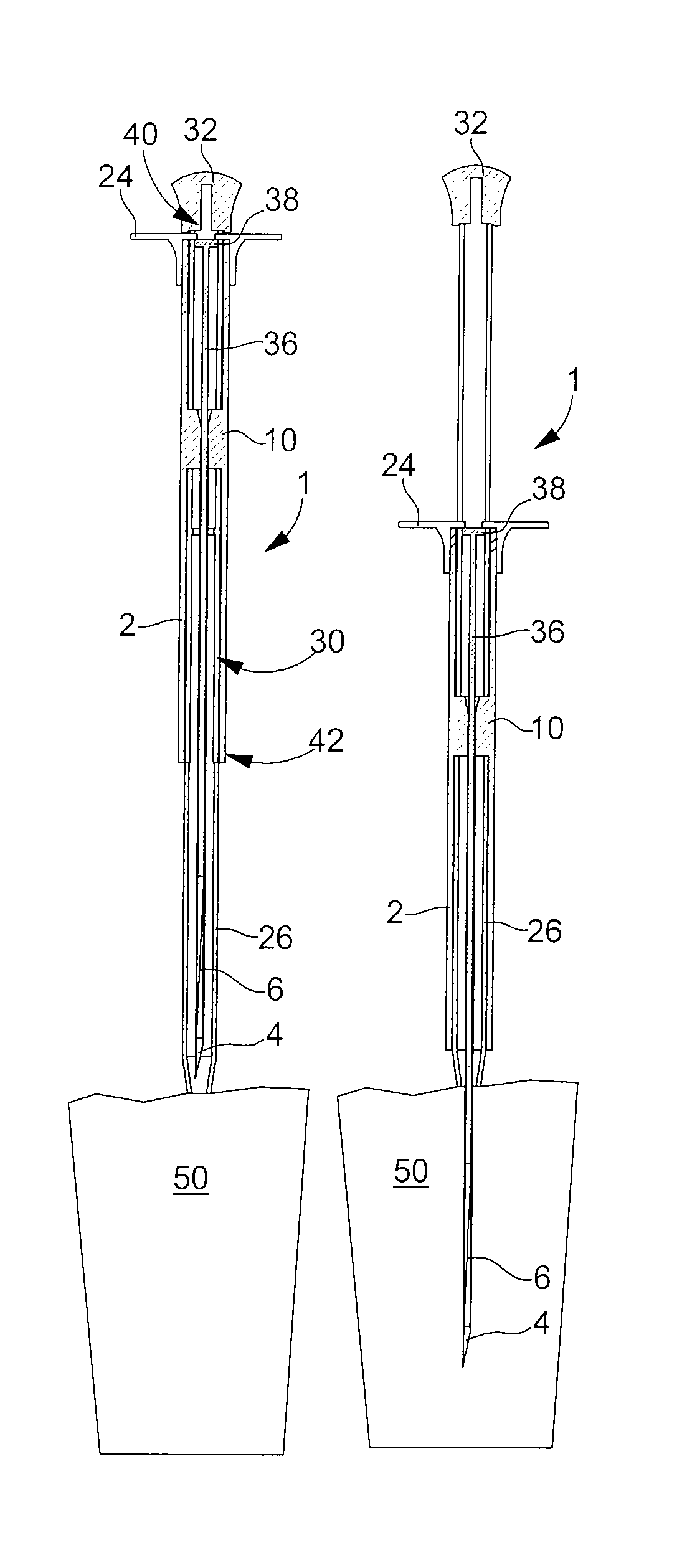
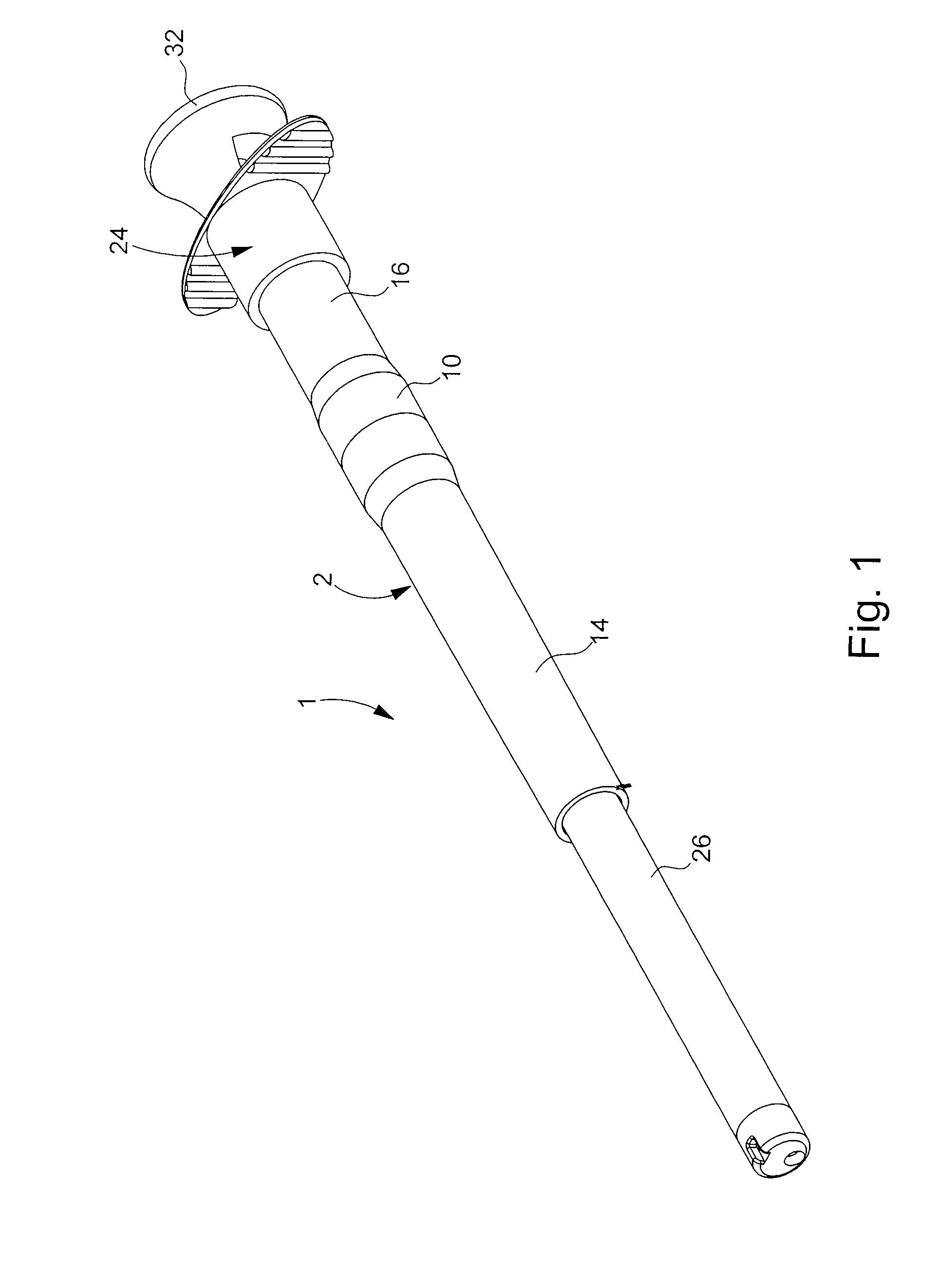
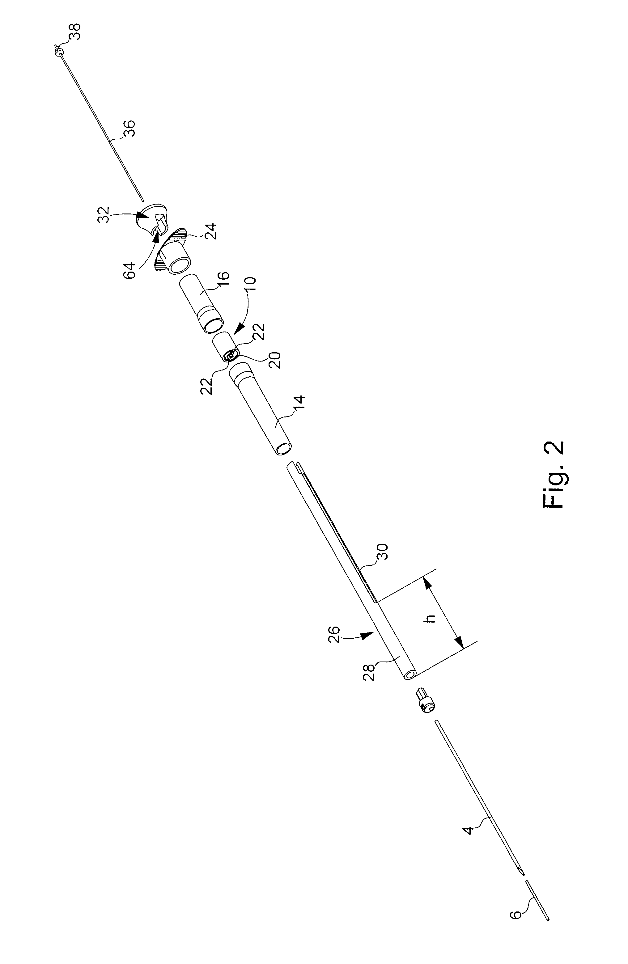
the injection device according to the invention will be described in relation to FIGS. 1 to 3B annexed to the present Patent Application.

Designated as a whole by the general reference numeral 1, the injection device shown in cross-section in FIGS. 3A and 3B includes a hollow main body 2 to which there is permanently fixed a hollow needle 4, into which an implant 6 is introduced for injection. Implants that can be injected with a device according to the invention include both solid or semi-solid pharmaceutical compounds and other non-therapeutic implants such as, for example, electronic chips used for identifying living beings.

Preferably, hollow needle 4 has at the distal end thereof a bevel 8 whose geometry is adapted to the anticipated application of injection device 1 and, in particular, to the method of administration. At the proximal end thereof, hollow needle 4 is fixedly mounted in a holding part 10. A through aperture 12 is made in holding part 10 for mounting needle 4. This ...


PUM


Abstract

The invention relates to a device which is used to inject an implant (6) into tissues (50). The inventive device is characterized in that it comprises: a main hollow body (2; 2′) having a hollow needle (4; 4′) fixed thereto, into which the implant (6) is introduced; a secondary body (26; 26′) which is disposed coaxially inside the main body (2; 2′) and which surrounds the needle (4; 4′); and a plunger rod (36; 36′) which can slide coaxially inside the hollow needle (4; 4′). The injection device (1; 1′) is arranged such that: (i) when it is pressed against the tissues (50), the main body (2; 2′) slides along the length of the secondary body (26; 26′) from a proximal position to a distal position such that the needle (4; 4′) can penetrate the tissues (50), whereby the movement of the main body (1; 1′) is accompanied by the concomitant movement of the plunger rod (36; 36′); and (ii) the plunger rod (36; 36′) remains fixed and maintains the implant (6) at the required depth in the tissues (50) until the needle (4; 4′) is removed therefrom when the main body (2; 2′) is returned from the distal position to the proximal position.

Description

This is a National Phase Application in the United States of International Patent Application No. PCT / EP2005 / 012247 filed Nov. 15, 2005, which claims priority on European Patent Application No. 04028413.5, filed Dec. 1, 2004. The entire disclosures of the above patent applications are hereby incorporated by reference.FIELD OF THE INVENTIONThe present invention concerns an injection device and, in particular, a device for the intramuscular or subcutaneous injection of an active pharmaceutical principal in the solid or semi-solid state usually called an implant. More generally, the invention applies to the injection of a solid body for a human or animal, such as for example electronic chips used for the identification of a living being.BACKGROUND OF THE INVENTIONAn injection device of the aforementioned type is already known from European Patent No. EP 0 783 342 in the name of the DELAB company. This type of injection device includes a main body in two parts to which a hollow needle i...

Claims


Application Information

Patent Timeline
IPC IPC(8): A61B17/20
CPCA61M37/0069
Inventor CHERIF-CHEIKH, ROLANDAUBERT, CHRISTOPHERIMLINGER, THIERRYBONACCI, FABRICEBARNEAUD, SERGE
Owner IPSEN PHARMA SAS
Learn More