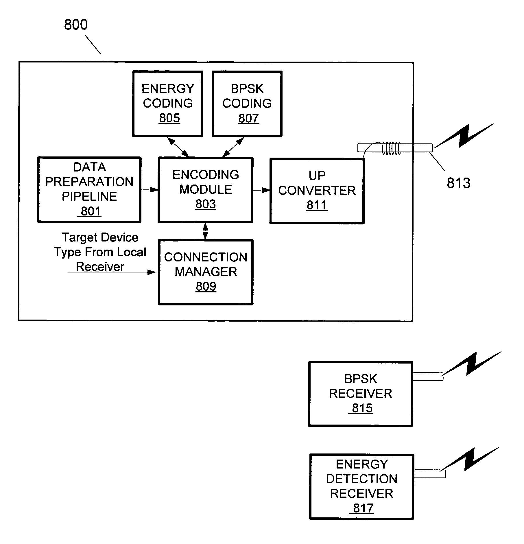
Energy detection receiver for UWB
a technology of energy detection receiver and receiver, which is applied in pulse technique, phase-modulated carrier system, instruments, etc., can solve the problems of reducing achieving the reduction of the complexity and power consumption reducing the usable bandwidth of the channel, and reducing the complexity of the uwb device. , the effect of simple energy detection circui
- Summary
- Abstract
- Description
- Claims
- Application Information
AI Technical Summary
Benefits of technology
Problems solved by technology
Method used
Image

Examples
Embodiment Construction
[0026]Embodiments of the invention will be described herein by reference to the Ultra Wideband (UWB) wireless communication technology, although it will be appreciated that the techniques described herein are useable with respect to devices implementing other communications technologies as well. UWB is sometimes alternatively referred to as impulse, baseband or zero-carrier technology. UWB is a wireless communications technology that transmits very short ultra-low power radio signals across a wide frequency spectrum. UWB receivers can translate the received burst by recognizing a particular pulse sequence sent by the transmitter. The FCC has defined UWB as including any signal that occupies more than 500 MHz or having more than 20% fractional bandwidth, in the 3.1 GHz to 10.6 GHz band. The bandwidth of a UWB signal is typically around 25% of the center frequency. For example, a “2 GHz” UWB signal may have a bandwidth of 500 MHz.
[0027]The spectrum allowed for UWB is 7500 MHz. This is...
PUM
 Abstract
Description
Claims
Application Information
 - R&D
- Intellectual Property
- Life Sciences
- Materials
- Tech Scout
- Unparalleled Data Quality
- Higher Quality Content
- 60% Fewer Hallucinations
Browse by: Latest US Patents, China's latest patents, Technical Efficacy Thesaurus, Application Domain, Technology Topic, Popular Technical Reports.
© 2025 PatSnap. All rights reserved.Legal|Privacy policy|Modern Slavery Act Transparency Statement|Sitemap|About US| Contact US: help@patsnap.com