
Systems and methods for acquisition and tracking of low CNR GPS signals

a technology of gps signals and receivers, applied in surveying and navigation, navigation instruments, instruments, etc., can solve the problems of limiting the use of conventional gps receivers for a number of applications, unable to reliably acquire gps signals, etc., and achieves low carrier-to-noise ratios (“cnr”), and low carrier-to-noise ratios

Inactive Publication Date: 2011-09-06
OHIO UNIV
View PDF41 Cites 23 Cited by
  • Summary
  • Abstract
  • Description
  • Claims
  • Application Information

AI Technical Summary

Benefits of technology

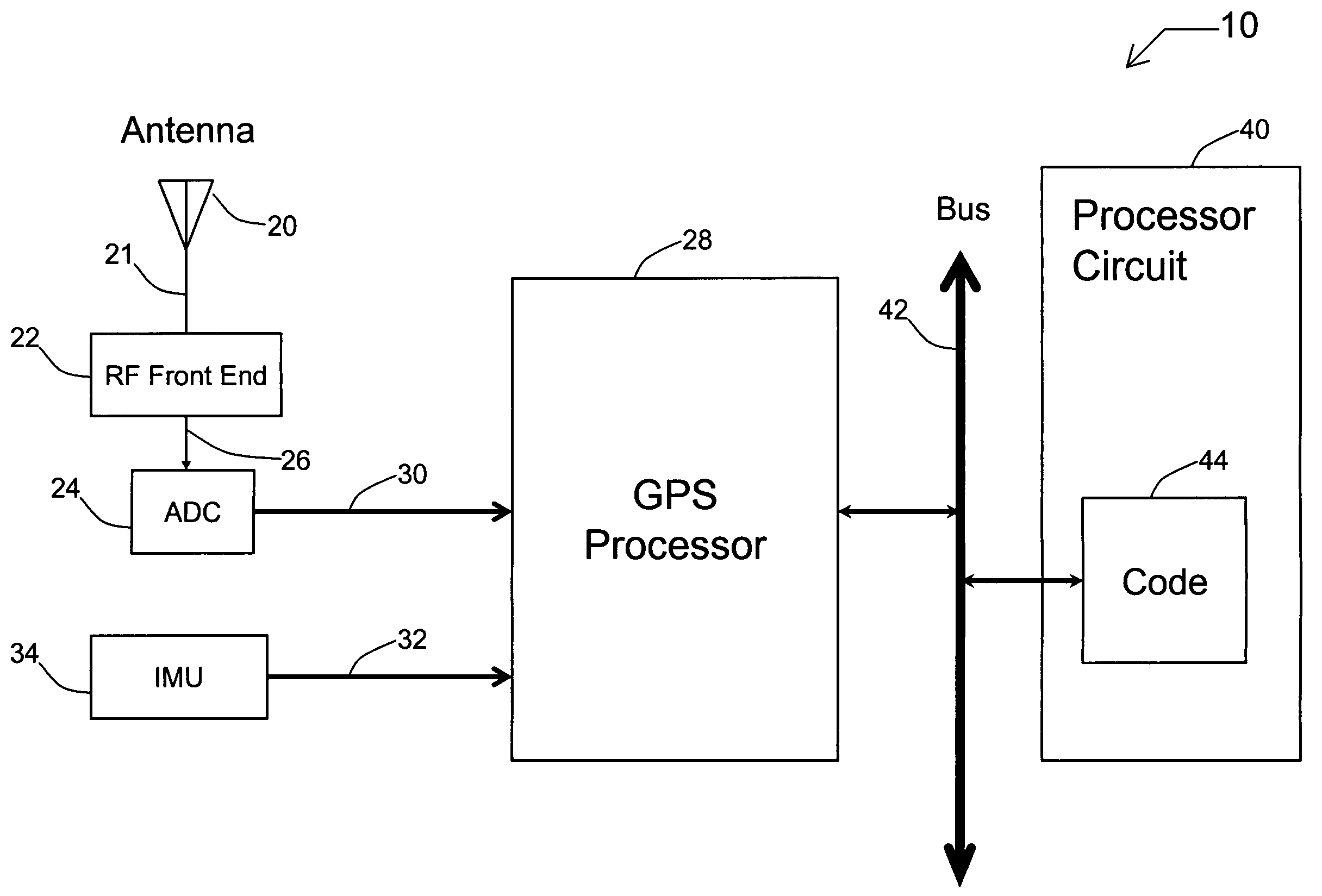
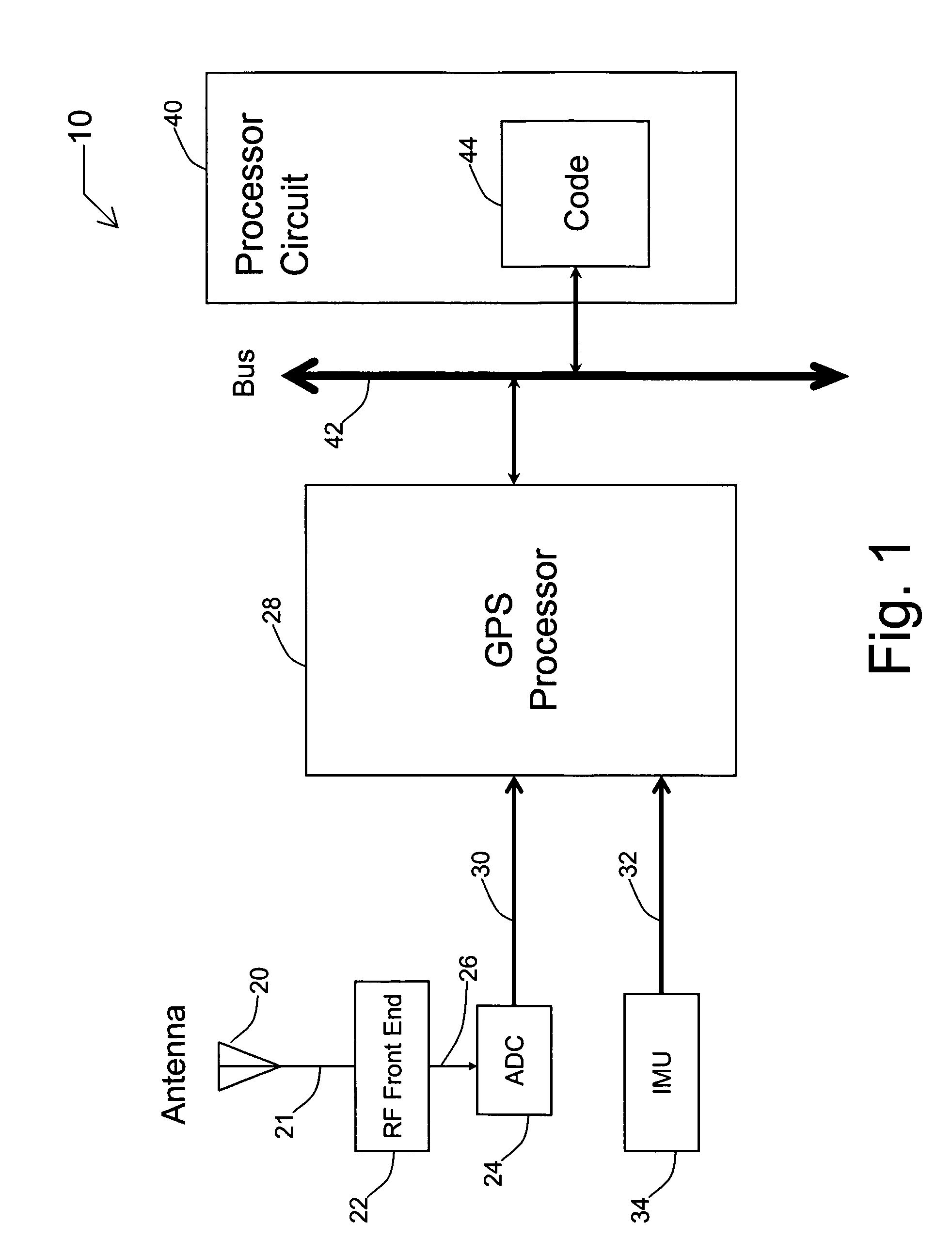
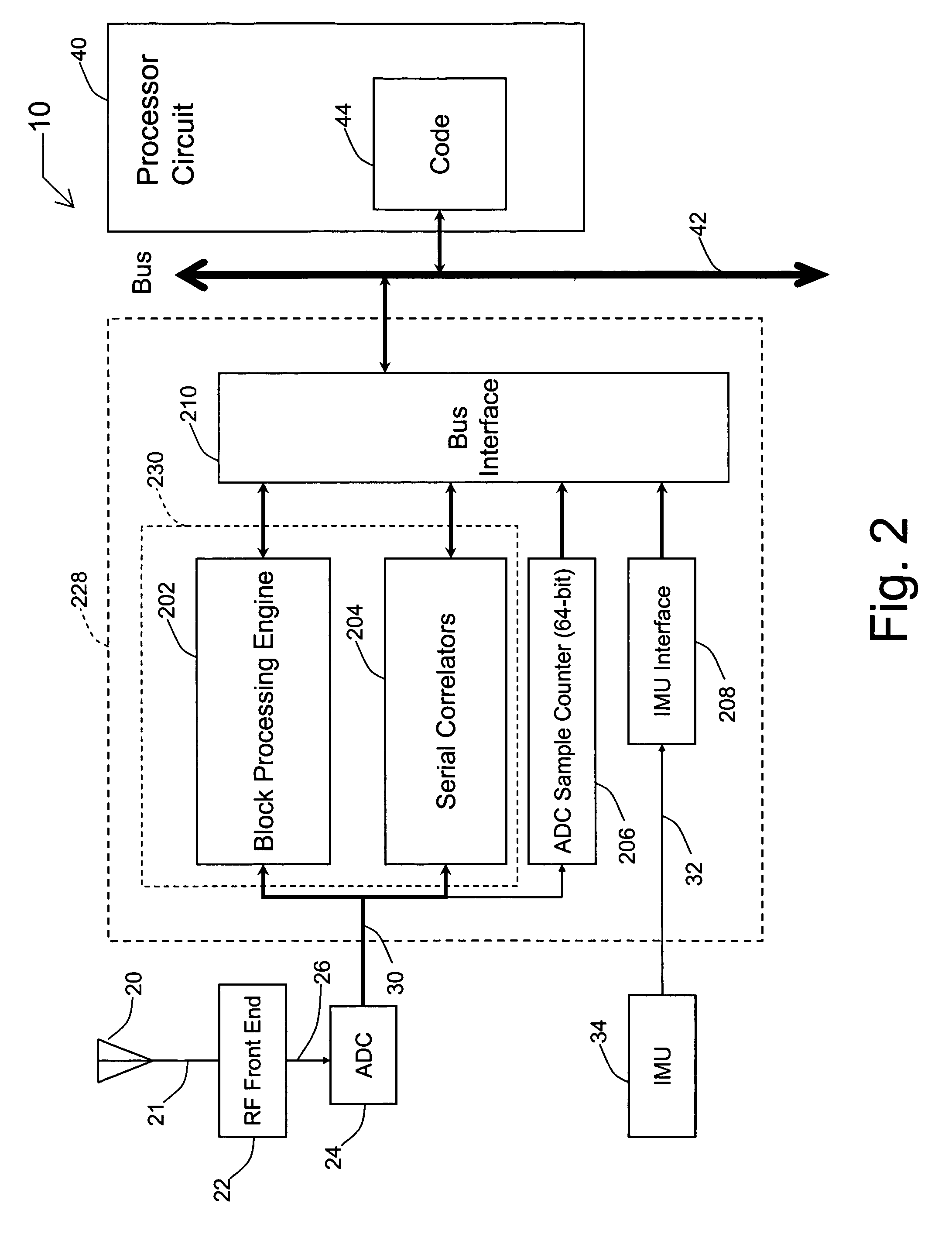
"The present invention provides a system and method for acquiring and tracking low carrier-to-noise ratio signals from multiple radio navigation satellites while the receiver is mobile. The system includes a radio frequency front-end for receiving satellite signals, an inertial measurement unit for providing inertial data, and a processor circuit for using the satellite and inertial data to continuously phase track the low CNR signals. The technical effect of the invention is to improve the accuracy and reliability of navigation signals in challenging conditions, such as urban canyons or high-speed driving, and to enhance the safety and reliability of navigation systems."

Problems solved by technology

As a result, GPS signals cannot be acquired and tracked reliably by such systems if the Carrier-to-Noise Ratio (CNR) is below 32 dB-Hz.
This limits the usage of conventional GPS receivers for a number of applications (e.g. indoor applications, precision agriculture applications near trees where the GPS signal is attenuated by the tree branches and foliage, or navigation in the presence of wideband interference).

Method used


Image

  • Systems and methods for acquisition and tracking of low CNR GPS signals
  • Systems and methods for acquisition and tracking of low CNR GPS signals
  • Systems and methods for acquisition and tracking of low CNR GPS signals

Examples


example 2

case, 10 frames are used for the bit detection; the bit error rate is 0.0054;

[0179]Example 3: 15 dB-Hz case, 20 frames are used for the bit detection; the bit error rate is 7.47·10−5;

[0180]Example 3: 15 dB-Hz case, 40 frames are used for the bit detection; the bit error rate is 1.97·10−8.

[0181]It is noted that Equation (22) does not consider the influence of word sign polarity resolution errors. The sign error rate is however negligible as compared to the bit error rate of the energy-based bit guessing. Specifically, sign error rate is computed as follows:

[0182]sign⁢⁢error⁢⁢rate=p·(1-p)+p2⁢⁢p=∑k=1224⁢C2424-k·ber0k·(1-ber0)24-k(23)

where 24 is the number of bits in the word excluding parity bits.

[0183]The corresponding frame sign error rate for a 15 dB-Hz case is 1.4095·10−5 whereas the bit error rate of the energy-based bit guessing (bero) equals 0.1304. Thus, frame sign errors serve as high-order effects and do not have to be considered to estimate the bit error rate of the bit deco...


PUM


Abstract

A receiver for continuous carrier phase tracking of low carrier-to-noise ratio (“CNR”) signals from a plurality of radio navigation satellites while the receiver is mobile. The receiver may have: a radio frequency (RF) front-end that provides satellite data corresponding to signals received from the plurality of radio navigation satellites; an inertial measurement unit (IMU) that provides inertial data; and a processor circuit in circuit communication with the RF front end and the IMU, the processor circuit being capable of using satellite data from the RF front-end and inertial data from the IMU to perform continuous carrier phase tracking of low CNR radio navigation satellite signals having a CNR of about 20 dB-Hz, while the receiver is mobile. The receiver may be a GPS receiver for continuous carrier phase tracking of low-CNR GPS signals.

Description

CROSS REFERENCE TO RELATED APPLICATIONS[0001]This application claims priority to and any other benefits of U.S. Provisional Application Ser. No. 60 / 616,445 filed on Oct. 6, 2004, which is entitled DEEPLY INTEGRATED GPS / IMU, and U.S. Provisional Application Ser. No. 60 / 647,543, filed on Jan. 27, 2005, and which is entitled SYSTEMS AND METHODS FOR ACQUISITION AND TRACKING OF LOW CNR GPS SIGNALS, both of which are incorporated herein by reference in their entireties.STATEMENT REGARDING FEDERALLY FUNDED RESEARCH[0002]This invention was funded, at least in part, by Federal Aviation Administration Aviation Research Co-Operative Agreement 98-G-002 (Local Area Augmentation System Research and Development). The federal government may have certain rights in this invention.FIELD OF THE INVENTION[0003]The present invention relates generally to the field of receivers for satellite-based radio navigation systems, e.g., Global Positioning System (“GPS”) receivers, and more specifically to receiver...

Claims


Application Information

Patent Timeline
Patent Type & Authority Patents(United States)
IPC IPC(8): G01S19/09G01C21/00G01S19/26G01S19/02G01S5/14G01S19/23G01S19/29G01S19/37G01S19/47
CPCG01S19/47G01S19/37G01S19/29G01S19/23G01S19/26G01S19/246
Inventor VAN GRAAS, FRANKSOLOVIEV, ANDREYGUNAWARDENA, SANJEEV
Owner OHIO UNIV
Learn More