
Capping layers for metal oxynitride TFTS

a technology of metal oxynitride and capping layers, which is applied in the direction of basic electric elements, electrical equipment, and semiconductor devices, can solve the problems of sub-threshold voltage, sub-threshold slope, and tft mobility may be negatively impacted, so as to optimize tft performance, the effect of reducing the risk of tft damag

Active Publication Date: 2011-09-06
APPLIED MATERIALS INC
View PDF127 Cites 48 Cited by
  • Summary
  • Abstract
  • Description
  • Claims
  • Application Information

AI Technical Summary

Problems solved by technology

If the capping layer contains too much hydrogen, nitrogen, or oxygen, the threshold voltage, sub threshold slope, and mobility of the TFT may be negatively impacted.

Method used


Image

  • Capping layers for metal oxynitride TFTS
  • Capping layers for metal oxynitride TFTS
  • Capping layers for metal oxynitride TFTS

Examples


Embodiment Construction

[0027]A capping layer may be deposited over the active channel of a TFT in order to protect the active channel from contamination. The capping layer may affect the performance of the TFT. If the capping layer contains too much hydrogen, nitrogen, or oxygen, the threshold voltage, (sub threshold slope, and mobility of the TFT may be negatively impacted. By controlling the ratio of the flow rates of the nitrogen, oxygen, and hydrogen containing gases, the performance of the TFT may be optimized. Additionally, the power density, capping layer deposition pressure, and the temperature may also be controlled to optimize the TFT performance.

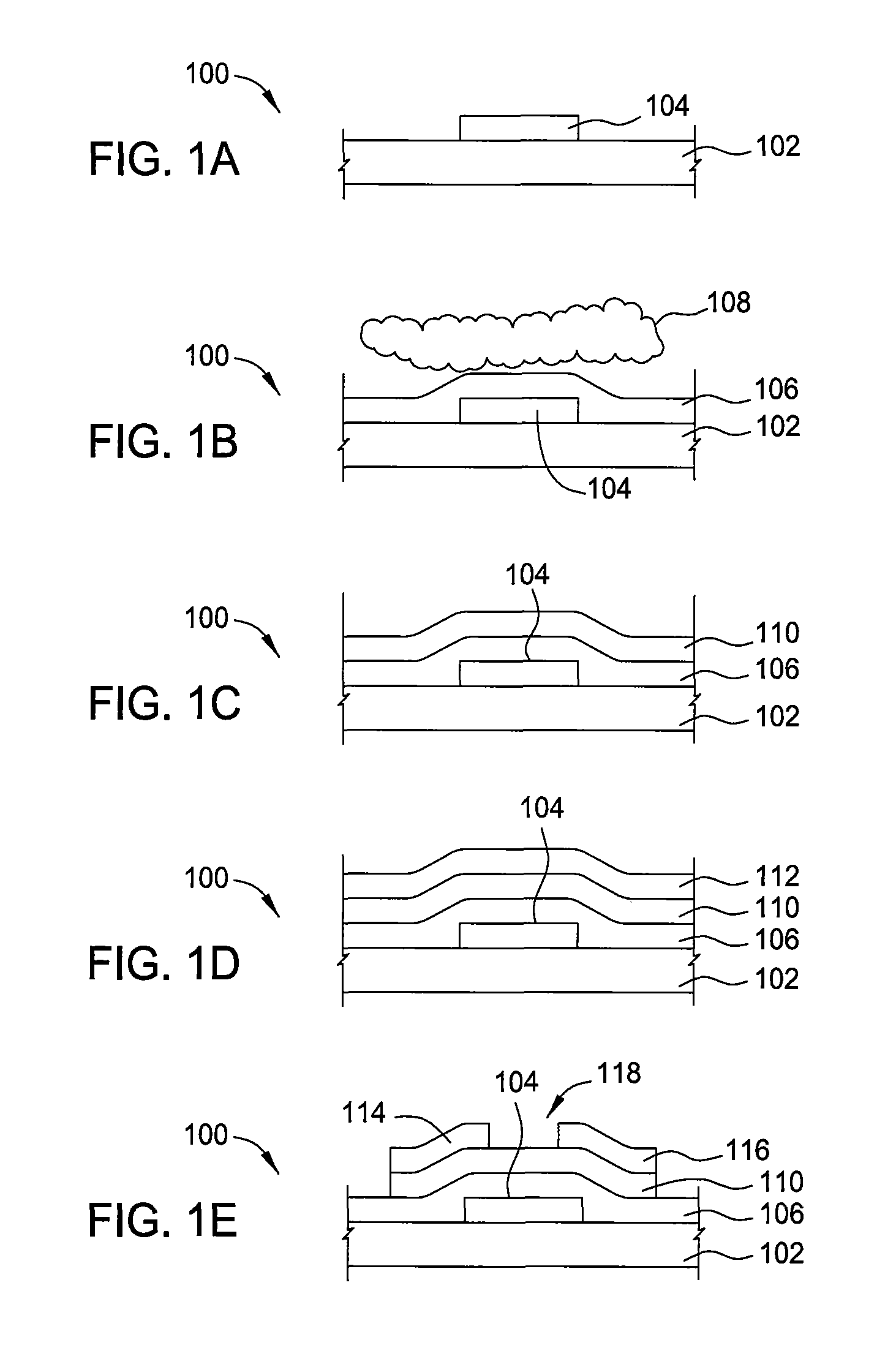
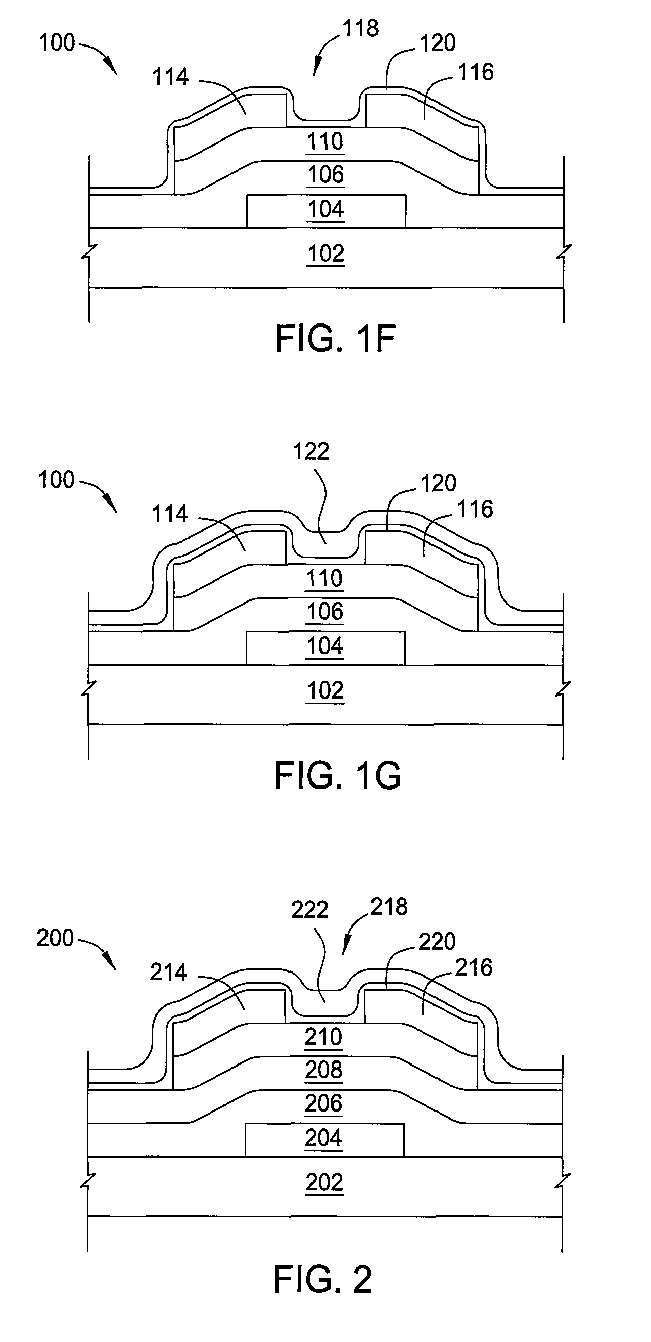
[0028]FIGS. 1A-1G are schematic cross sectional views of a TFT 100 according to one embodiment of the invention at various stages of fabrication. The TFT may comprise a substrate 102. In one embodiment, the substrate 102 may comprise glass. In another embodiment, the substrate 102 may comprise a polymer. In another embodiment, the substrate 102 may comp...


PUM


Abstract

A capping layer may be deposited over the active channel of a thin film transistor (TFT) in order to protect the active channel from contamination. The capping layer may affect the performance of the TFT. If the capping layer contains too much hydrogen, nitrogen, or oxygen, the threshold voltage, sub threshold slope, and mobility of the TFT may be negatively impacted. By controlling the ratio of the flow rates of the nitrogen, oxygen, and hydrogen containing gases, the performance of the TFT may be optimized. Additionally, the power density, capping layer deposition pressure, and the temperature may also be controlled to optimize the TFT performance.

Description

CROSS-REFERENCE TO RELATED APPLICATIONS[0001]This application claims benefit of U.S. Provisional Patent Application Ser. No. 61 / 077,831 (APPM / 013582L), filed Jul. 2, 2008, U.S. Provisional Patent Application Ser. No. 61 / 117,744 (APPM / 013582L02), filed Nov. 25, 2008 and U.S. Provisional Patent Application Ser. No. 61 / 117,747 (APPM / 013582L03), filed Nov. 25, 2008, all of which are herein incorporated by reference.GOVERNMENT RIGHTS IN THIS INVENTION[0002]This invention was made with Government support under Agreement No. DAAD19-02-3-0001 awarded by ARL. The Government has certain rights in the Invention.BACKGROUND OF THE INVENTION[0003]1. Field of the Invention[0004]Embodiments of the present invention generally relate to a method of fabricating thin film transistors (TFTs).[0005]2. Description of the Related Art[0006]Current interest in TFT arrays is particularly high because these devices may be used in liquid crystal active matrix displays (LCDs) of the kind often employed for compu...

Claims


Application Information

Patent Timeline
Patent Type & Authority Patents(United States)
IPC IPC(8): H01L21/336
CPCH01L21/02521H01L21/02554H01L29/7869H01L21/02631H01L21/02565H01L29/66742H01L29/78606
Inventor YE, YAN
Owner APPLIED MATERIALS INC
Learn More