
Method for correcting the measured concentrations of gas components in drilling mud

a technology of gas components and concentrations, which is applied in the direction of survey, instruments, borehole/well accessories, etc., can solve the problems of divergent predictions, measurement of surface gas trap values, and measurement of gas trap values that are not representative of the gas composition of drilling fluid or formation fluid at depth

Inactive Publication Date: 2011-09-06
CHEVROU USA INC
View PDF18 Cites 10 Cited by
  • Summary
  • Abstract
  • Description
  • Claims
  • Application Information

AI Technical Summary

Benefits of technology

"The present invention provides a method for characterizing the fluid present in a subsurface earth formation by extracting gas components from drilling mud containing the fluid and gases, measuring the gas trap value for each gas component, and calculating the corrected gas trap value by dividing the gas trap value by the relative response factor for each gas component. This allows for the accurate measurement of the gas components in the drilling mud and the formation fluid. The invention also provides a system for performing the method and a computer program for controlling the system. The technical effect of the invention is to provide a reliable and accurate method for characterizing the formation fluid during drilling operations."

Problems solved by technology

Unfortunately, there are numerous problems associated with surface gas trap measurements.
As a result, measured gas trap values are not representative of the gas composition of the drilling fluid or the formation fluid at depth.
Additionally, uncorrected gas trap values can lead to widely divergent predictions of total fluid properties, including GOR determinations.

Method used


Image

  • Method for correcting the measured concentrations of gas components in drilling mud
  • Method for correcting the measured concentrations of gas components in drilling mud
  • Method for correcting the measured concentrations of gas components in drilling mud

Examples


Embodiment Construction

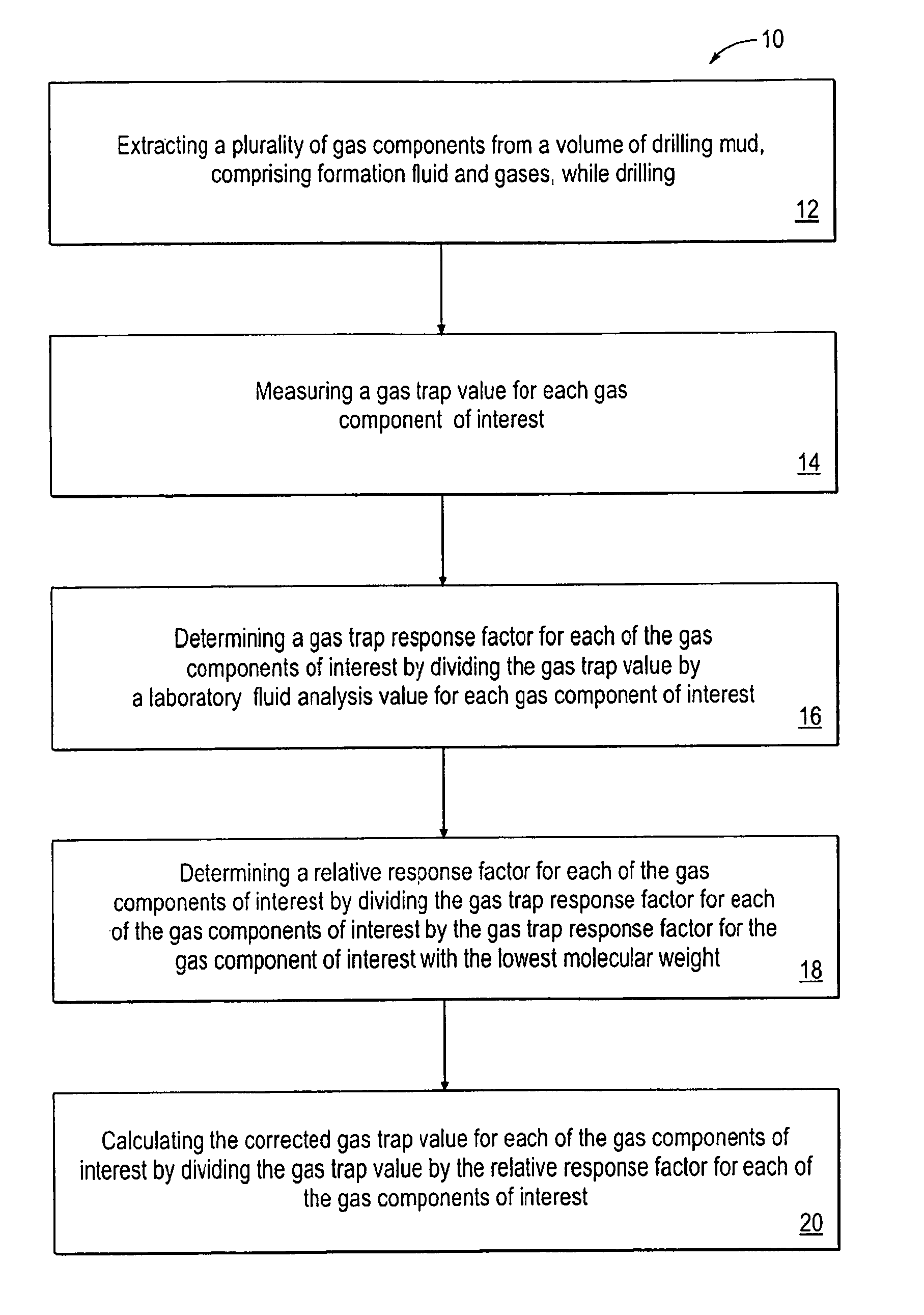
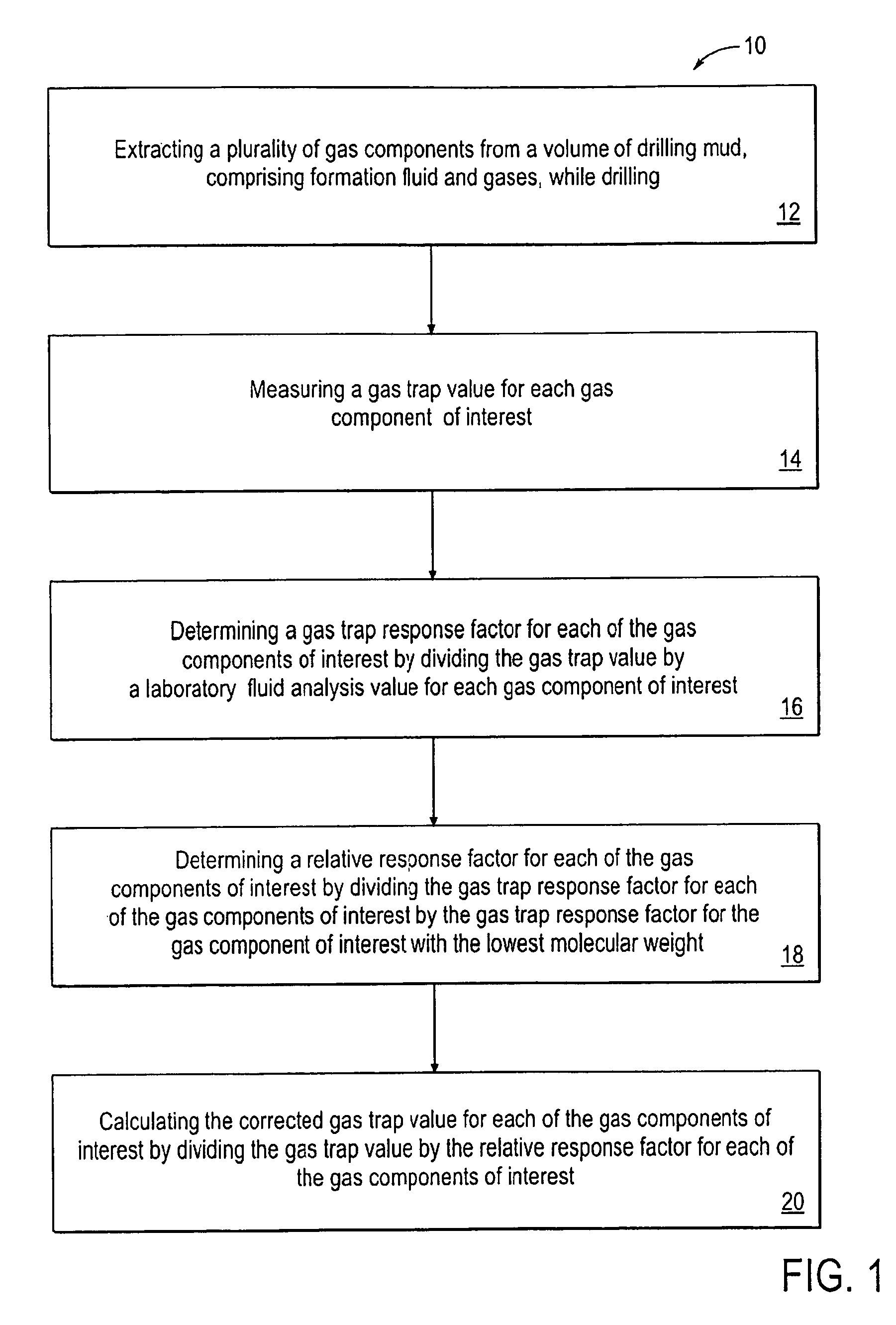
[0015]Referring to FIG. 1, a method 10 for characterizing formation fluid present in a subsurface earth formation is shown. During drilling operations, a plurality of formation gas components are extracted 12 from a volume of circulating drilling mud which contains formation fluid and gases. In one embodiment, the formation gas components are extracted from the mud by mechanical agitation in a gas trap located at the surface. Gas trap values 14 for each gas component of interest is measured. Separation and quantification of the different formation gas components of interest, typically any of the light hydrocarbon gases (methane through pentane), is measured by means of an in-line gas-chromatograph or gas-chromatograph mass-spectrometer, and / or a total hydrocarbon analyzer. While the means for such an analysis is preferably a gas chromatograph equipped with a flame ionization detector for hydrocarbon gases, it will be appreciated that any means for analyzing the gas mixture compositi...


PUM

PropertyMeasurementUnit
volumeaaaaaaaaaa
molecular weightaaaaaaaaaa
gas chromatographyaaaaaaaaaa

Abstract

A method of characterizing formation fluid present in a subsurface earth formation during drilling using methods for correcting the measured concentrations of gas components in drilling mud. Gas trap values for the gas components of interest, light hydrocarbons, are measured during mud logging and are corrected using relative response factors, determined from laboratory fluid analysis values and relative extraction efficiency values. The relative response factors for each gas component of interest can be used for correcting additional gas trap values measured in the same well or for correcting gas trap values measured in surrounding wells utilizing a similar drilling fluid. The corrected gas trap values for each of the gas components of interest can be utilized to calculate gas / oil ratios for characterizing the formation fluid from the volume of drilling mud.

Description

FIELD OF THE INVENTION[0001]The present invention relates generally to characterizing formation fluid present in a subsurface earth formation during drilling and more particularly to methods for correcting the measured concentrations of gas components in drilling mud.BACKGROUND OF THE INVENTION[0002]In oil or gas well drilling operations, drilling fluid (or “mud”) is continuously circulated through the inside of the drill pipe and out the drill bit then back up to the surface. Drilling mud is typically made up of clays, chemical additives and an oil or water base. This fluid has several purposes: 1) controlling formation pressure; 2) cleaning the well bore of formation debris; 3) lubricating, cooling, and cleaning the drill bit and drill string; 4) stabilizing the well bore; and 5) limiting the loss of drilling mud to the subsurface formation.[0003]In cleaning the well bore, the circulating drilling mud removes the drill cuttings as well as formation fluid trapped in the pore space ...

Claims


Application Information

Patent Timeline
Patent Type & Authority Patents(United States)
IPC IPC(8): E21B49/00G01N33/24
CPCG01N33/24G01N2030/8854E21B49/005G01N33/2823
Inventor HANSON, SCOTT A.
Owner CHEVROU USA INC
Learn More