
Systems and methods for transmitter calibration

a transmitter and receiver technology, applied in the field of receiver calibration, can solve problems such as direct conversion transceivers, impairments such as dc offset and iq mismatch, and carrier leakage, and complicate the problem of miniaturization

Inactive Publication Date: 2011-08-30
SAMSUNG ELECTRO MECHANICS CO LTD
View PDF3 Cites 18 Cited by
  • Summary
  • Abstract
  • Description
  • Claims
  • Application Information

AI Technical Summary

Benefits of technology

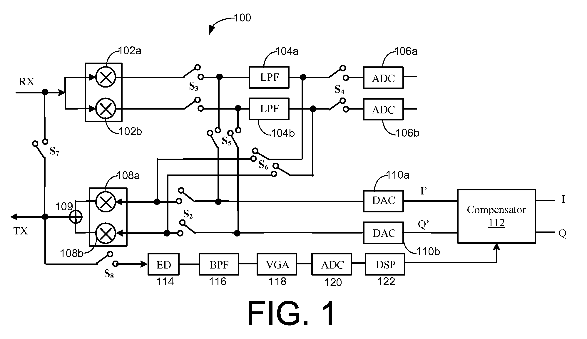
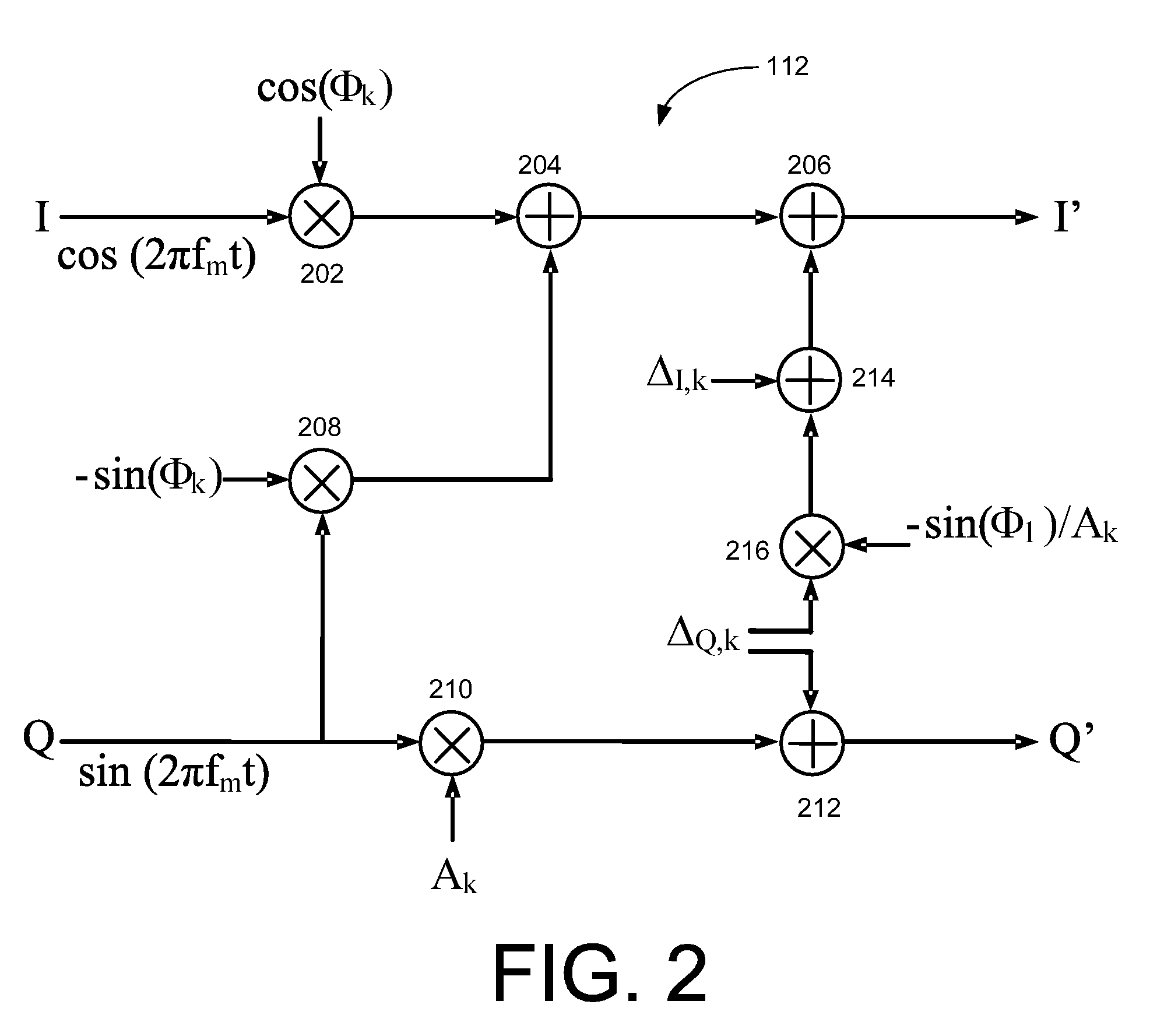
[0004]Effective method to compensate for the IQ mismatch and DC offsets / carrier leakage in wireless time-division duplex (TDD) transceivers with shared baseband filters is presented. Overall calibration strategy for transmitter with test tone is described first. Then, detailed IQ mismatch and DC offsets / carrier leakage calibration method with an envelope detector (ED) is presented. The calibration method exploits inherent architecture of the reconfigurable transceiver with shared baseband filters by directly estimating mixer phase mismatch and compensate for the DC offsets / carrier leakage more effectively.

Problems solved by technology

The main drawbacks of a direct conversion transceiver are impairments such as DC offsets and IQ mismatch.
For example, the multiple-input multiple-output (MIMO) communication protocol, which requires a large number of duplicate RF and analog circuits as well as complex baseband digital system in a system-on-chip (SoC) implementation, complicates the issues of miniaturization, mismatches, and carrier leakages.

Method used


Image

  • Systems and methods for transmitter calibration
  • Systems and methods for transmitter calibration
  • Systems and methods for transmitter calibration

Examples


Embodiment Construction

[0014]Example embodiments of the invention now will be described more fully hereinafter with reference to the accompanying drawings, in which some, but not all embodiments of the invention are shown. Indeed, these inventions may be embodied in many different forms and should not be construed as limited to the embodiments set forth herein; rather, these embodiments are provided so that this disclosure will satisfy applicable legal requirements. Like numbers refer to like elements throughout.

[0015]Example embodiments of the invention may provide system and methods for calibration of transmitters, such as those utilized for wireless time-division duplex (TDD) transceivers. According to an example embodiment of the invention, the calibration systems and methods may compensate for IQ mismatches and / or DC offsets / carrier leakages associated with the transmitter.

[0016]FIG. 1 illustrates an example system for a transceiver 100 such as a reconfigurable wireless time-division duplex (TDD) tra...


PUM


Abstract

Systems and methods may be provided for transmitter calibration. The systems and methods may include providing one or more radio frequency (RF) test signals at an output of a transmitter, wherein the one or more RF test signals are based upon IQ baseband test signals, and applying an envelope detector to the one or more test signals to obtain one or more characteristic signals from the one or more RF test signals, where the one or more characteristic signals includes one or more first harmonic components and one or more second harmonic components associated with the one or more RF test signals. The systems and methods may further include analyzing the one or more second harmonic components to determine one or more IQ mismatch compensation parameters, and analyzing the one or more first harmonic components to determine one or more carrier leakage or DC offset compensation parameters.

Description

FIELD OF THE INVENTION[0001]Embodiments of the invention relate generally to radio frequency (RF) transmitters, and more particularly, to the calibration of RF transmitters.BACKGROUND OF THE INVENTION[0002]Direct conversion transceiver architectures are a popular choice for RF integrated circuit (IC) implementation in modern wireless communication applications due to their compact size and low power consumption as compared to a traditional heterodyne transceiver. The main drawbacks of a direct conversion transceiver are impairments such as DC offsets and IQ mismatch. Modern wireless communication protocols including wireless LAN (e.g., IEEE 802.11 a / g / n) utilize orthogonal frequency division multiplexing (OFDM) with high-order (e.g., 64-QAM) constellation sizes to exchange high data-rate information over time dispersive wireless channels. The IQ mismatch (insufficient image rejection) and carrier leakage (or DC offset) at the transmitter side should be well-controlled so that the tr...

Claims


Application Information

Patent Timeline
Patent Type & Authority Patents(United States)
IPC IPC(8): H03C1/62
CPCH04B17/14
Inventor KIM, DUKHYUNHUR, YOUNG SIKKIM, JEONG HOON
Owner SAMSUNG ELECTRO MECHANICS CO LTD
Learn More