
Substrate for mass spectrometry and mass spectrometry method

a mass spectrometry and substrate technology, applied in the field of substrate, can solve the problems of long analysis time period, non-uniform detection, low sensitivity of detecting analyte that is not easily ionized, etc., and achieve the effect of effective enhancement of electric field, enhanced electric field, and increased energy of laser beams

Active Publication Date: 2011-08-30
FUJIFILM CORP
View PDF8 Cites 3 Cited by
  • Summary
  • Abstract
  • Description
  • Claims
  • Application Information

AI Technical Summary

Benefits of technology

[0010]Further, it is another object of the present invention to provide a substrate for mass spectrometry that can use a lower-power laser beam in mass spectrometry and that can separate the analytes from each other.
[0031]The first substrate for mass spectrometry of the present invention includes a first reflective member that is semi-transmissive and semi-reflective, a transparent member, and a second reflective member that is reflective, which are sequentially provided to form an optical resonator. Therefore, light that has passed through the first reflective member and entered the transparent member repeats reflection between the first reflective member and the second reflective member, and multiple reflection occurs. This multiple reflection light effectively induces multiple interference, which causes resonance. Further, the resonance effectively enhances the electric field on the surface of the first reflective member that contacts with a sample containing an analyte for mass spectrometry. Therefore, in a spectrometry method, in which the analyte is ionized and desorbed by irradiation with a laser beam, the energy of the laser beam is increased by the enhanced electric field. Hence, it is possible to ionize and to desorb the analyte by irradiation with a low-power laser beam, compared with the conventional method. Since the energy of the laser beam per se can be reduced, damage to the analyte can be prevented, and the cost of the apparatus can be reduced.
[0032]Further, a sample separation portion at which surface interaction occurs between the sample separation portion and a plurality of analytes contained in a sample liquid is provided on the surface of the first reflective member. Therefore, it is possible to separate the plurality of analytes contained in the sample liquid to different positions from each other. Since it is possible to prevent fluctuation in the ionization efficiency caused by interference and inhibition between the analytes, high-sensitivity mass spectrometry is possible.
[0033]In the second substrate for mass spectrometry of the present invention, the surface of the substrate is a rough metal surface that excites localized plasmons by irradiation with a laser beam and that generates a hot spot. Therefore, it is possible to effectively enhance the electric field on the surface of the substrate. Therefore, in an analysis method, in which the analyte is ionized and desorbed by irradiation with a laser beam, the energy of the laser beam is increased by the enhanced electric field. Hence, it is possible to ionize and to desorb the analyte by irradiation with a low-power laser beam, compared with the conventional method. Since the energy of the laser beam per se can be reduced, damage to the analyte can be prevented, and the cost of the apparatus can be reduced.
[0034]Further, a sample separation portion at which surface interaction occurs with a plurality of analytes contained in a sample liquid is provided on the surface of the substrate. Therefore, it is possible to separate the plurality of analytes contained in the sample liquid to different positions from each other. Therefore, it is possible to prevent fluctuation in the ionization efficiency caused by the interference and inhibition between the analytes. Hence, high-sensitivity mass spectrometry becomes possible.
[0035]As described above, the substrate for mass spectrometry of the present invention makes it possible to perform mass spectrometry using a low-energy laser beam, and the present invention can provide a mass spectrometry method in which high-sensitivity mass spectrometry is possible.

Problems solved by technology

However, since some analytes are easily ionized while some other analytes are not easily ionized, if ionization process is performed on a mixture of such analytes to ionize the analytes that have different ionization characteristics from each other at the same time, the sensitivity of detecting the analyte that is not easily ionized is lower than the sensitivity of detecting the analyte that is easily ionized.
Consequently, a problem of non-uniform detection occurs.
Therefore, an analysis time period is long, and loss of the analyte occurs due to adsorption of the analyte to the column.
However, in these methods for mass spectrometry, a high-power laser beam is necessary to ionize a substance adsorbed on the surface of a substrate and to desorb the substance from the surface of the substrate.
If the high-power laser beam is used, there is a risk that the analyte is damaged.
Further, since a high-power light source is needed to irradiate the analyte with the high-power laser beam, there is a problem that the cost of the apparatus becomes high.
However, in the method, the analytes are spread and blurred by application of the matrix material.
However, separation of the analytes, as described above, is impossible.
However, improvement of the ionization efficiency by plasmons is neither described in detail nor sufficiently studied.

Method used


Image

  • Substrate for mass spectrometry and mass spectrometry method
  • Substrate for mass spectrometry and mass spectrometry method
  • Substrate for mass spectrometry and mass spectrometry method

Examples


first embodiment

of Substrate for Mass Spectrometry

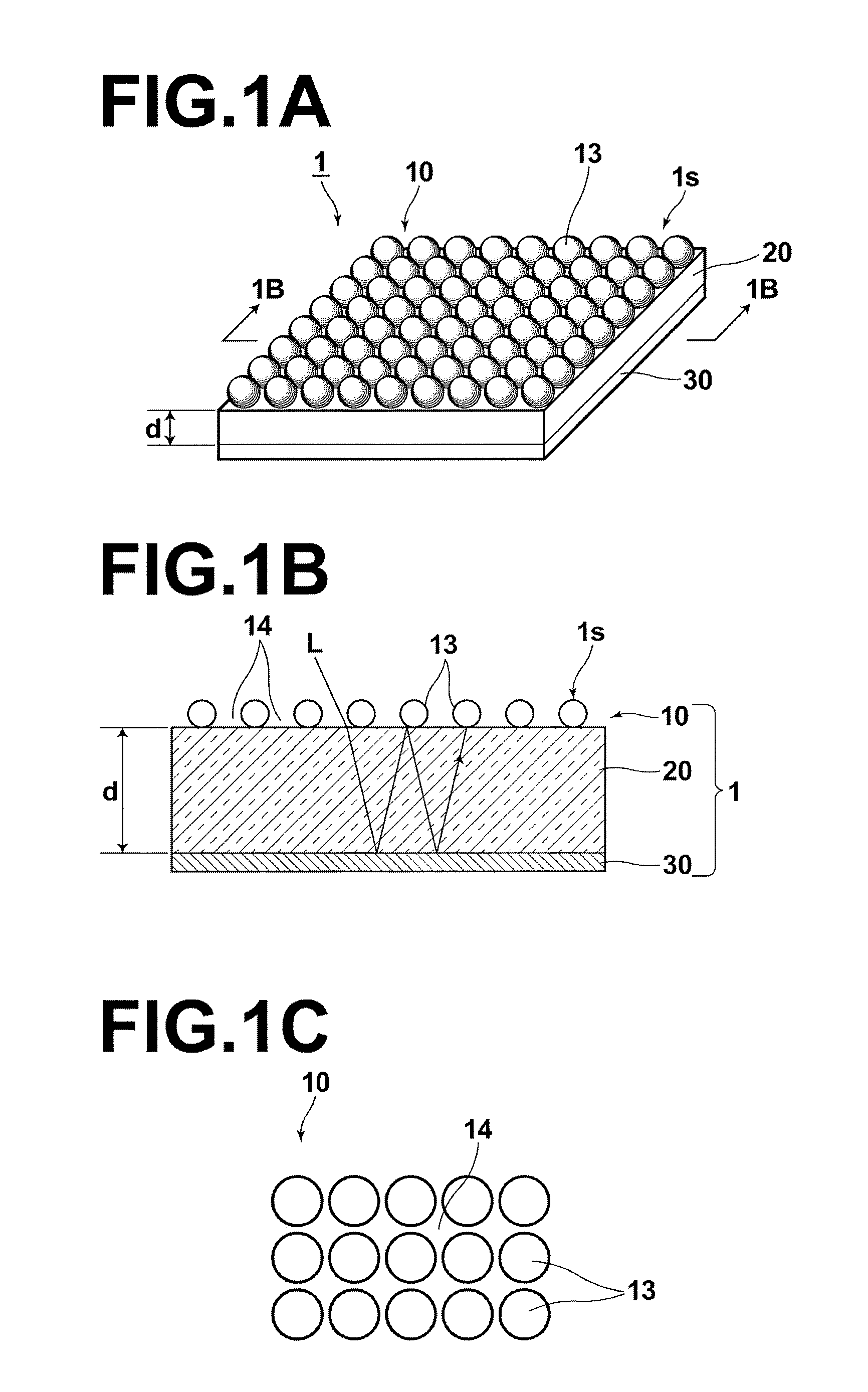
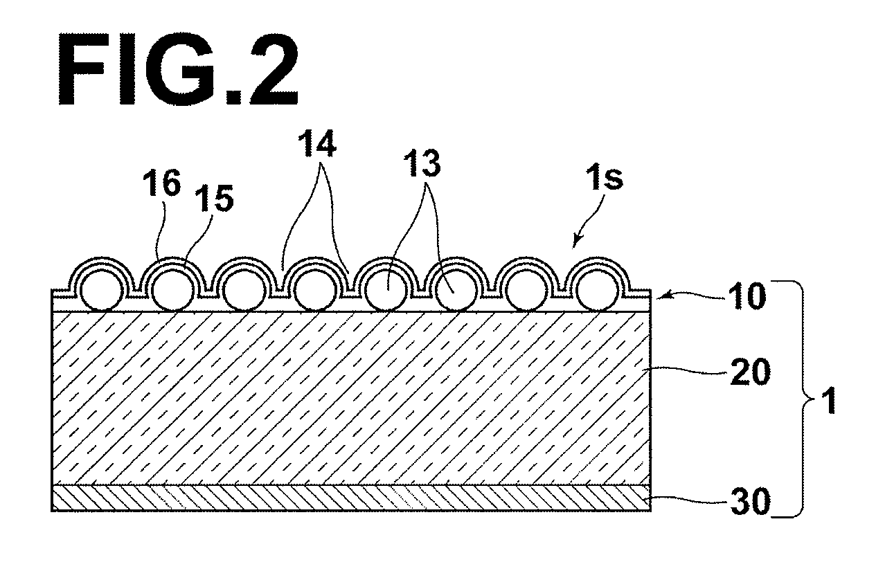
[0057]A substrate for mass spectrometry according to a first embodiment of the present invention will be described with reference to FIGS. 1A through 1C. The substrate for mass spectrometry according to the present embodiment forms an optical resonator. FIG. 1A is a perspective view, and FIG. 1B is a sectional view in the thickness direction of the substrate (sectional view along 1B-1B line). FIG. 1C is a schematic top view illustrating the arrangement of metal particles, which will be described later.

[0058]As illustrated in FIG. 1A, a substrate 1 for mass spectrometry of the present embodiment has device structure including a first reflective member 10, a transparent member 20, and a second reflective member 30. The first reflective member 10, the transparent member 20, and the second reflective member 30 are sequentially provided from the laser-beam-L-entering side (upper side in FIG. 1A). The first reflective member 10 is semi-transmissive and s...

second embodiment

of Substrate for Mass Spectrometry

[0106]With reference to FIGS. 3A through 3D, a substrate for mass spectrometry according to a second embodiment of the present invention will be described. The substrate for mass spectrometry of the present embodiment forms an optical resonator in a manner similar to the first embodiment. FIGS. 3A through 3C are perspective views illustrating the process of producing the substrate for mass spectrometry. FIG. 3D is a sectional diagram illustrating the substrate for mass spectrometry. In the present embodiment, the same reference numerals will be assigned to elements corresponding to the elements of the first embodiment, and explanation of such elements will be omitted.

[0107]As illustrated in FIGS. 3C and 3D, a substrate 2 for mass spectrometry of the present embodiment has the first reflective member 10, the transparent member 20 and the second reflective member 30 in a manner similar to the first embodiment. The first reflective member 10, the tran...

third embodiment

of Substrate for Mass Spectrometry

[0128]With reference to FIG. 4, a substrate for mass spectrometry according to a third embodiment of the present invention will be described. FIG. 4 is a sectional diagram of the substrate for mass spectrometry. The substrate for mass spectrometry according to the third embodiment forms an optical resonator in a manner similar to the substrates for mass spectrometry according to the first embodiment and the second embodiment. In the present embodiment, same reference numerals will be assigned to elements corresponding to the elements of the first embodiment, and explanation of the elements will be omitted.

[0129]As illustrated in FIG. 4, a substrate 3 for mass spectrometry of the present embodiment has the first reflective member 10, the transparent member 20 and the second reflective member 30 in a manner similar to the first embodiment. The first reflective member 10, the transparent member 20 and the second reflective member 30 are sequentially pr...


PUM


Abstract

A substrate for mass spectrometry includes a first reflective member that is semi-transmissive / semi-reflective, a transparent member, and a second reflective member that is reflective, sequentially provided to form an optical resonator. The optical resonator includes, on a surface of the first reflective member, a sample separation portion at which surface interaction occurs with a plurality of analytes contained in a sample liquid. The analytes are separated on the sample separation portion to perform mass spectrometry on each of the analytes. A sample in contact with the surface of the first reflective member is irradiated with laser beam L to generate resonance in the optical resonator, and an electric field on the surface of the first reflective member is enhanced by the resonance. The enhanced electric field is utilized to ionize analytes S in the sample and to desorb the analytes S from the surface.

Description

BACKGROUND OF THE INVENTION[0001]1. Field of the Invention[0002]The present invention relates to a substrate (base plate) for mass spectrometry and a mass spectrometry method. In the mass spectrometry, a substance fixed (immobilized) on a surface of the substrate is irradiated with a laser beam to be desorbed from the surface, and the desorbed substance is captured to perform mass spectrometry.[0003]2. Description of the Related Art[0004]As an analysis method used to identify a substance or the like, a mass spectrometry method is well known. In the mass spectrometry method, an analyte (a substance to be analyzed, an analysis target) is ionized, and identified based on the mass-to-charge ratio of the analyte. For example, in time-of-flight mass spectrometry (TOF-MS, time-of-flight mass spectroscopy), an ionized analyte is caused to fly for a predetermined distance between high-voltage electrodes, and the mass of the analyte is analyzed based on the time of flight.[0005]As ionization ...

Claims


Application Information

Patent Timeline
Patent Type & Authority Patents(United States)
IPC IPC(8): H01J49/26
CPCH01J49/0418
Inventor IKEDA, MORIHITOMURAKAMI, NAOKI
Owner FUJIFILM CORP
Learn More