
Method and system for stokes polarization imaging

a polarization imaging and polarization system technology, applied in the direction of optical radiation measurement, instruments, measurement devices, etc., can solve the problems of limiting the use of still targets and laboratory measurements, reducing the achievable image resolution, and the mechanical rotation of the polarizer not allowing high speed measurements

Inactive Publication Date: 2011-08-23
BOSSA NOVA TECH
View PDF4 Cites 23 Cited by
  • Summary
  • Abstract
  • Description
  • Claims
  • Application Information

AI Technical Summary

Problems solved by technology

However, the mechanical rotation of a polarizer does not allow high speed measurements.
This limits their use mainly to still targets and laboratory measurements.
These systems do not have moving parts so that they can be very fast.
However, the achievable image resolution is reduced because of pixel interpolation to compensate for the fact that each pixel only sees one polarization state.
Systems with separated cameras do not have moving parts, allow high resolution, but are very sensitive to alignment and also expensive as they require at least 3 times the hardware of a single camera.

Method used


Image

  • Method and system for stokes polarization imaging
  • Method and system for stokes polarization imaging
  • Method and system for stokes polarization imaging

Examples


Embodiment Construction

[0020]Specific embodiments of the present disclosure will now be described in detail with reference to the accompanying Figures. Like elements in the various Figures are denoted by like reference numerals for consistency.

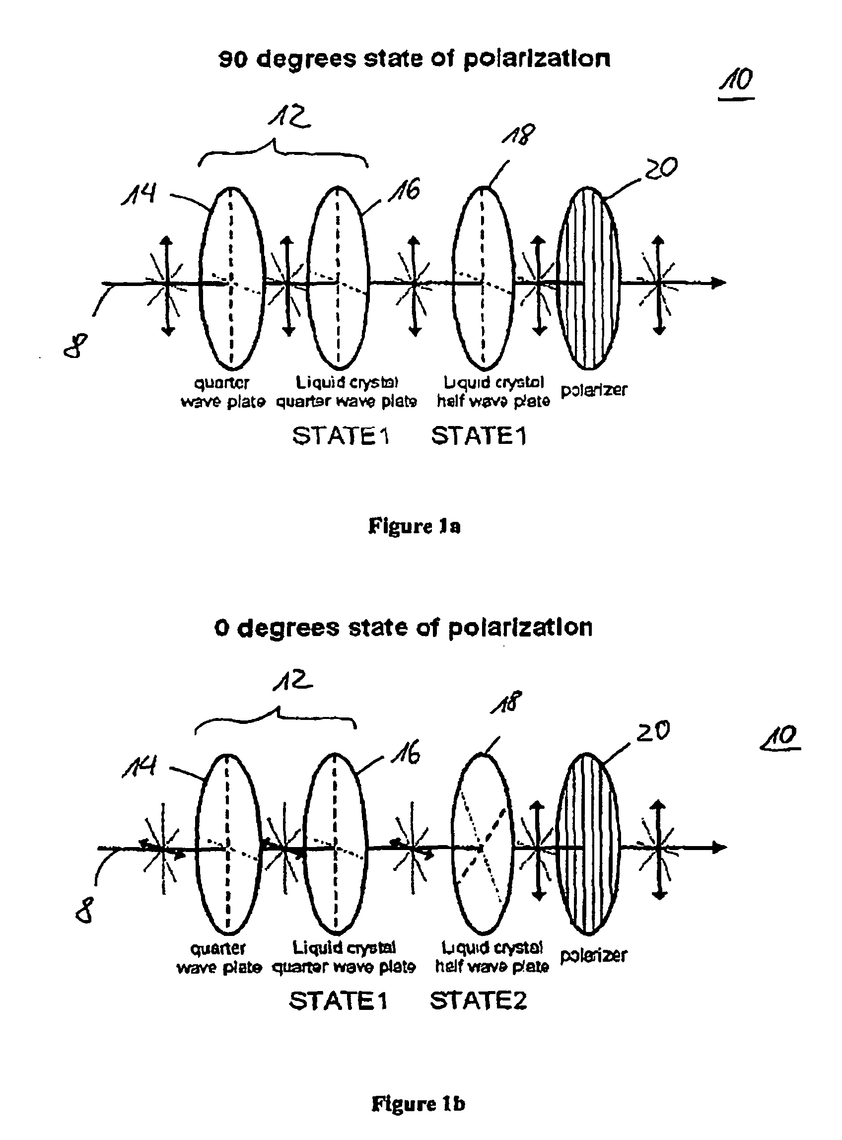
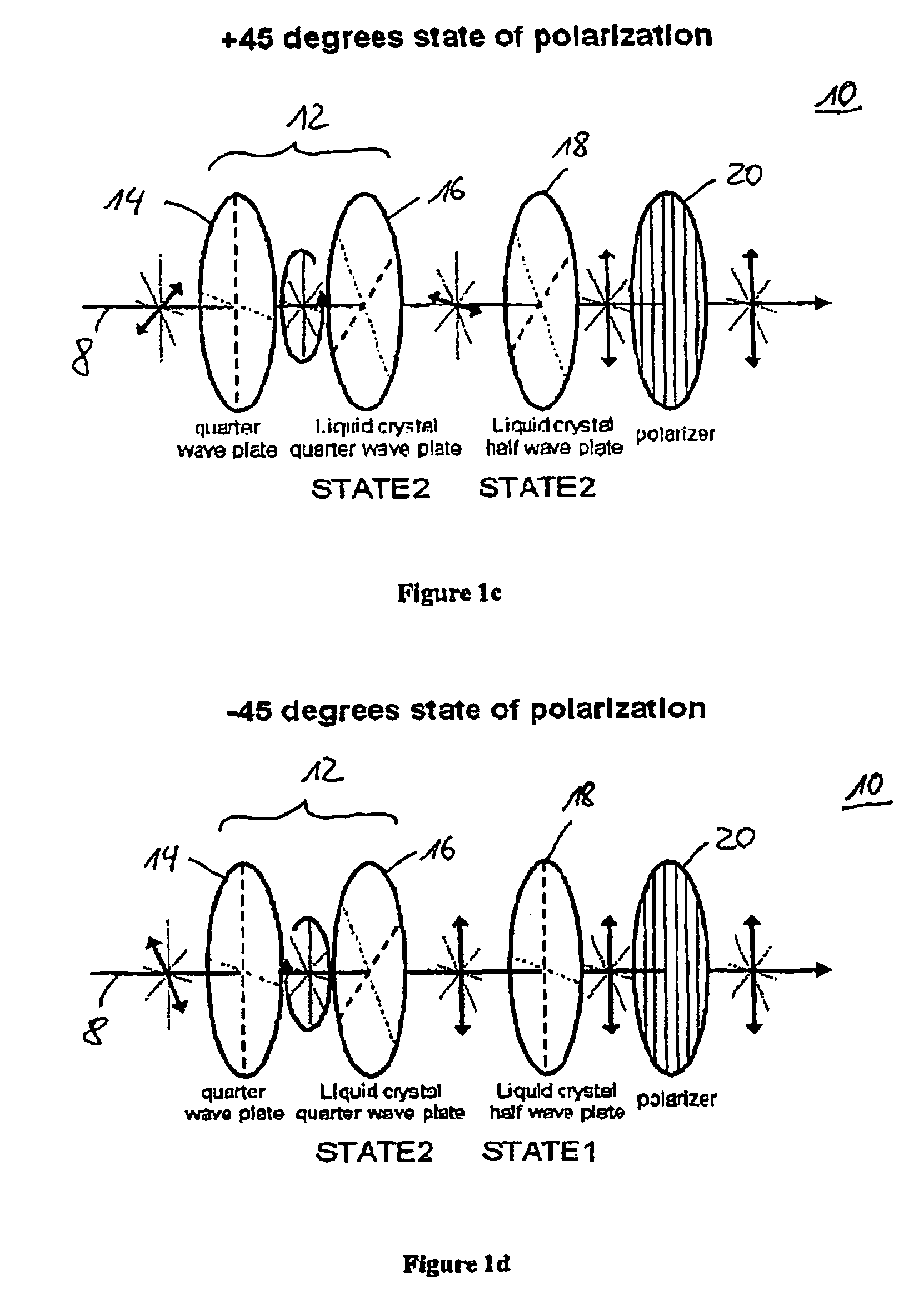
[0021]In general, embodiments of the present disclosure relate to a device and a method for reliable, high-speed linear polarization imaging of a scene. More specifically, embodiments of the present disclosure provide a method and a device for linear polarization imaging, whereby the imaging device includes a polarization modulator allowing for high image resolution and fast switching times.

[0022]Referring to FIG. 1a, the polarization modulator 10 of the polarization imaging device according to embodiments of the present disclosure is shown. The polarization modulator 10 includes a first and a second polarization rotation block 12, 18, which are aligned with respect to each other, and a fixed polarizer 20. The first polarization rotation block 12 includes a fixed qu...


PUM


Abstract

A device and a method for high-speed linear polarization imaging of a scene are disclosed. The device comprises a polarization modulator for modulating the polarization of light emitted from the scene in order to obtain at least three linear polarization states of the light. The polarization modulator comprises a polarizer, a first polarization rotation block comprising a fixed quarter-wave plate and a first liquid crystal operating as a quarter-wave plate, and a second polarization rotation block comprising a second liquid crystal operating as a half-wave plate. Each of the first and second liquid crystals are switchable between two states, thereby providing the at least three polarization states to the polarization modulator. The device further comprises a sensor adapted to capture image frames of the light from the scene at each polarization state of the polarization modulator.

Description

BACKGROUND OF INVENTION[0001]1. Field of the Invention[0002]The present invention relates generally to a system and a method for determining linear Stokes parameters and particularly to high-speed linear polarization imaging of a scene.[0003]2. Background Art[0004]There are several ways to describe the polarization of light. The polarization can be totally described by 4 parameters. There are many sets of 4 parameters that can be used. The most natural parameters are the Stokes parameters, which represent the intensity of the light, the amount of linearly polarized light, the orientation of the linear polarization, and the amount of circularly polarized light (with the sign of this parameter depending on the rotation of the light). The Stokes parameters are regrouped in the Stokes vector,[0005]S=(S0S1S2S3),wherein S0 is the total intensity of the light, and S1=I0−I90 is the intensity of light through a horizontal polarizer minus the intensity of light through a vertical polarizer. F...

Claims


Application Information

Patent Timeline
Patent Type & Authority Patents(United States)
IPC IPC(8): G01J4/00
CPCG01J4/04
Inventor LEFAUDEUX, NICOLAS
Owner BOSSA NOVA TECH
Learn More