Method and apparatus for a drip tray screen
a drip tray and drip tray technology, applied in the direction of defrosting, instruments, domestic cooling apparatus, etc., can solve the problems of unaccounted for strainer or trap type, unsuitable for dumping or misdelivery of ice in drip tray, and additional problems
- Summary
- Abstract
- Description
- Claims
- Application Information
AI Technical Summary
Benefits of technology
Problems solved by technology
Method used
Image
Examples
first embodiment
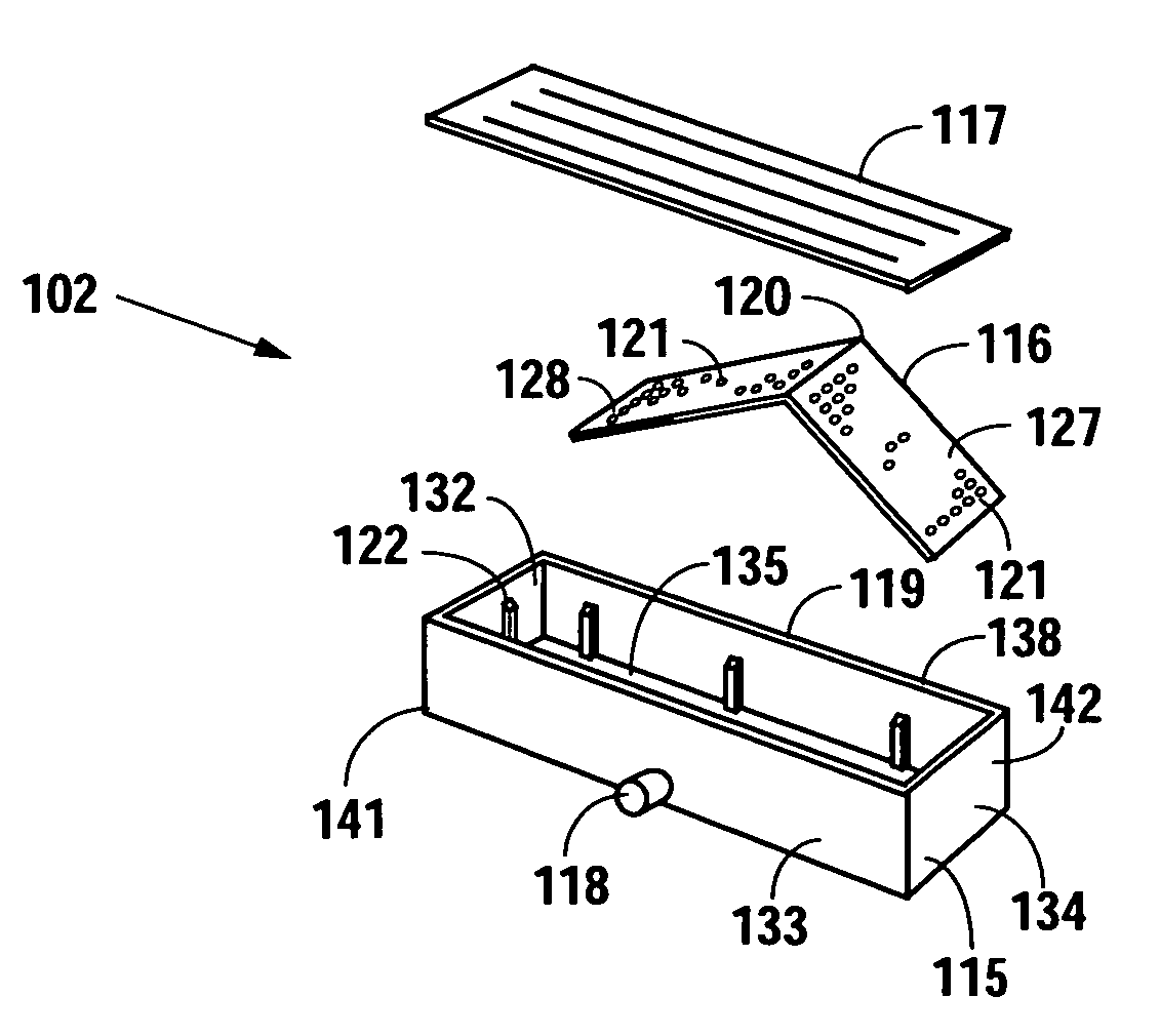
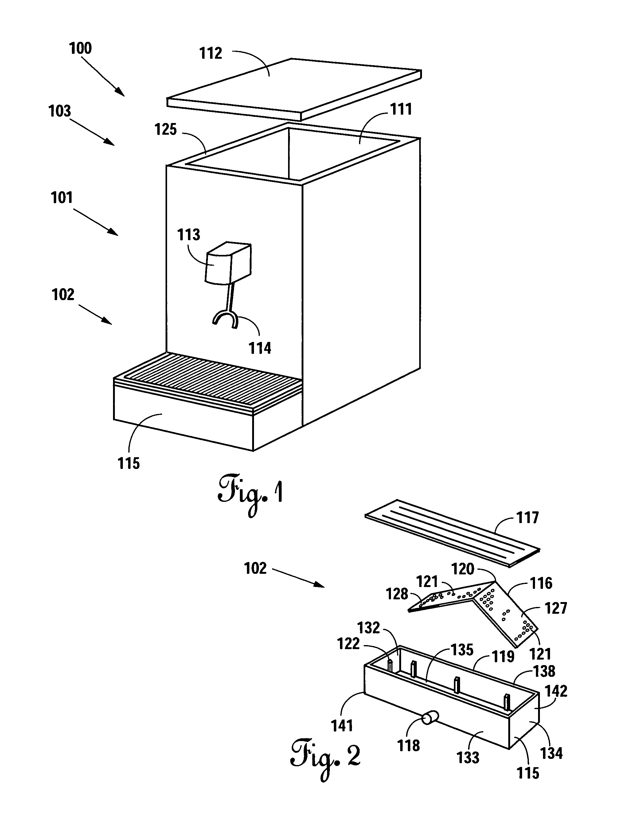
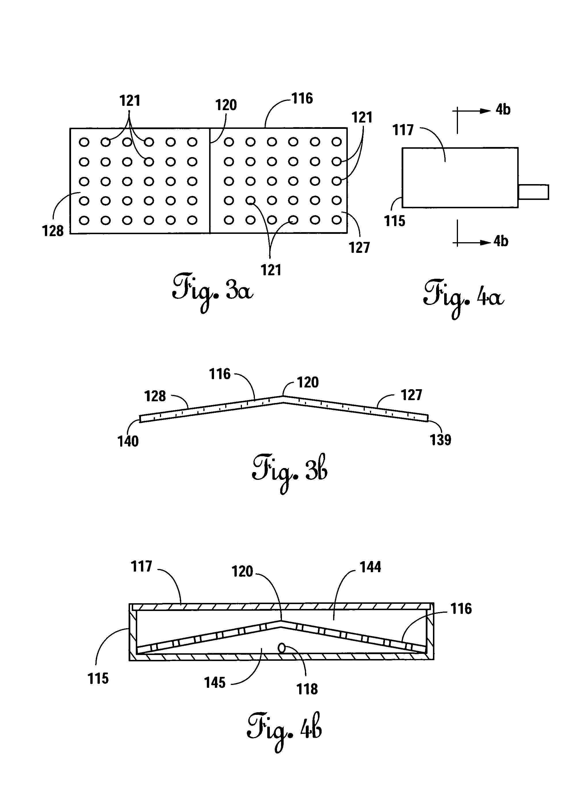
[0047]The drip tray assembly 102 includes a tray 115, a trap 116, and a cup rest 117. The tray 115 includes first through fourth walls 131-134 disposed vertically and a floor panel 135 that form a tray capable of holding fluids as well as solid products. The tray further includes a first end 141 and a second end 142. The floor panel 135 is disposed horizontally and connects to each of the walls 131-134 to create a tray having an interior cavity 119 with an inlet 138. The tray 115 may be formed from virtually any material that is compatible with beverages resists corrosion. Illustratively, in this first embodiment, the tray 115 is formed from acetal butyl styrene. The tray 115 may further include a drain port 118 disposed in a wall 133 nearest the product dispenser 100 or in the floor panel 135. In this particular example, the drain port 118 includes a fitting for attaching to a disposal system (not shown), such as a sewer system or septic system. Accordingly, when the drain port 118...
second embodiment
[0072]FIG. 8e provides a flowchart illustrating the method steps for inserting and removing a drip tray trap 416, according to this Optimally, an operator grasps a handling feature 429 in each hand, as shown in step 25. The operator then moves to step 30, wherein the operator places the trap 416 into the interior cavity 119 of a drip tray 115, such that the handling features 529-530 are disposed upward. In step 35, the operator installs the cup rest 117 above the trap. Upon installation, the trap 416 deflects foreign objects and ice particles, as described in step 40. After use, the operator removes the cup rest 117 to access the trap 416, step 45. Once the cup rest 117 has been removed, the operator removes foreign objects deflected by the trap, step 50. Upon the successful removal of the foreign objects, the operator grasps the handling features 429 and 430, step 55. The operator then lifts the handling features 429 and 430, thereby lifting the trap 416 out of the interior cavity...
PUM
 Abstract
Description
Claims
Application Information
 - R&D
- Intellectual Property
- Life Sciences
- Materials
- Tech Scout
- Unparalleled Data Quality
- Higher Quality Content
- 60% Fewer Hallucinations
Browse by: Latest US Patents, China's latest patents, Technical Efficacy Thesaurus, Application Domain, Technology Topic, Popular Technical Reports.
© 2025 PatSnap. All rights reserved.Legal|Privacy policy|Modern Slavery Act Transparency Statement|Sitemap|About US| Contact US: help@patsnap.com


