
Moving object detection apparatus and method

a detection apparatus and moving object technology, applied in the field of moving object detection apparatus and method, can solve the problems of difficult to effectively detect moving objects using a single image-based technique, ineffective surveillance, and inability to provide dynamic security support for image-based moving object detection techniques deployed on fixed cameras. to achieve the effect of improving the reliability of moving object detection and enhancing the background subtraction

Inactive Publication Date: 2011-08-16
IND TECH RES INST
View PDF37 Cites 171 Cited by
  • Summary
  • Abstract
  • Description
  • Claims
  • Application Information

AI Technical Summary

Benefits of technology

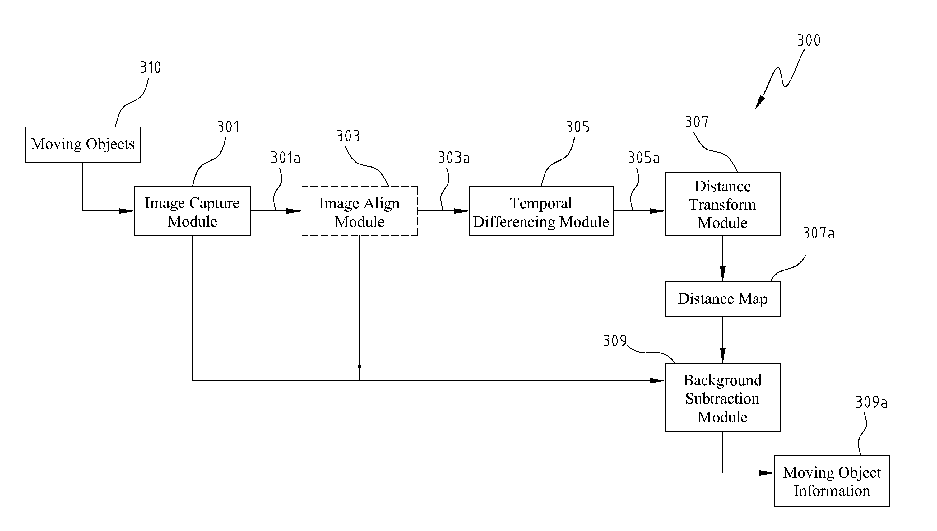
The present invention provides an apparatus and method for detecting moving objects in real-time using a movable camera platform or a fixed camera platform. The apparatus includes an image capture module, an image alignment module, a temporal differencing module, a distance transform module, and a background subtraction module. The method involves capturing images at different times, aligning the images, applying temporal differencing to generate a difference image, transforming the difference image into a distance map, and applying the distance map to background subtraction technology to compare with a current captured image to obtain the moving object information. The technical effects of the invention include improved reliability of moving object detection and better understanding of the information of the detected moving objects.

Problems solved by technology

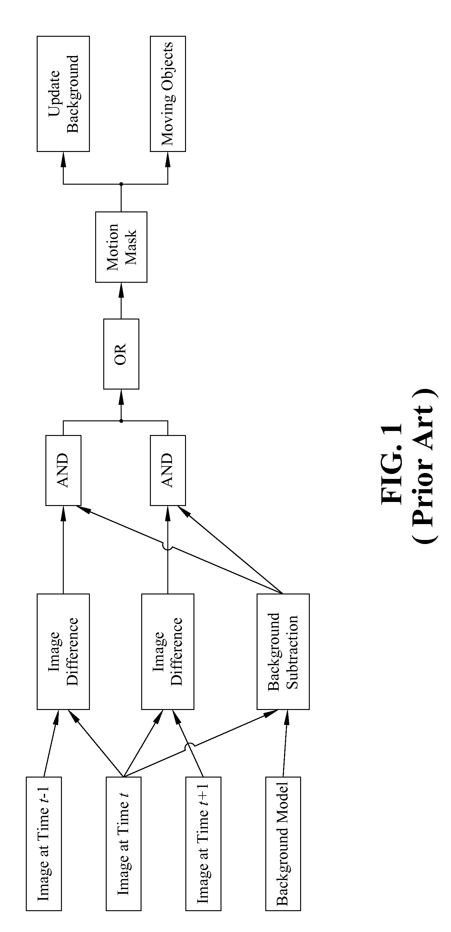
However, image-based moving object detection technique deployed on a fixed camera usually cannot provide dynamic security support.
In a restricted surveillance area, the surveillance is often ineffective.
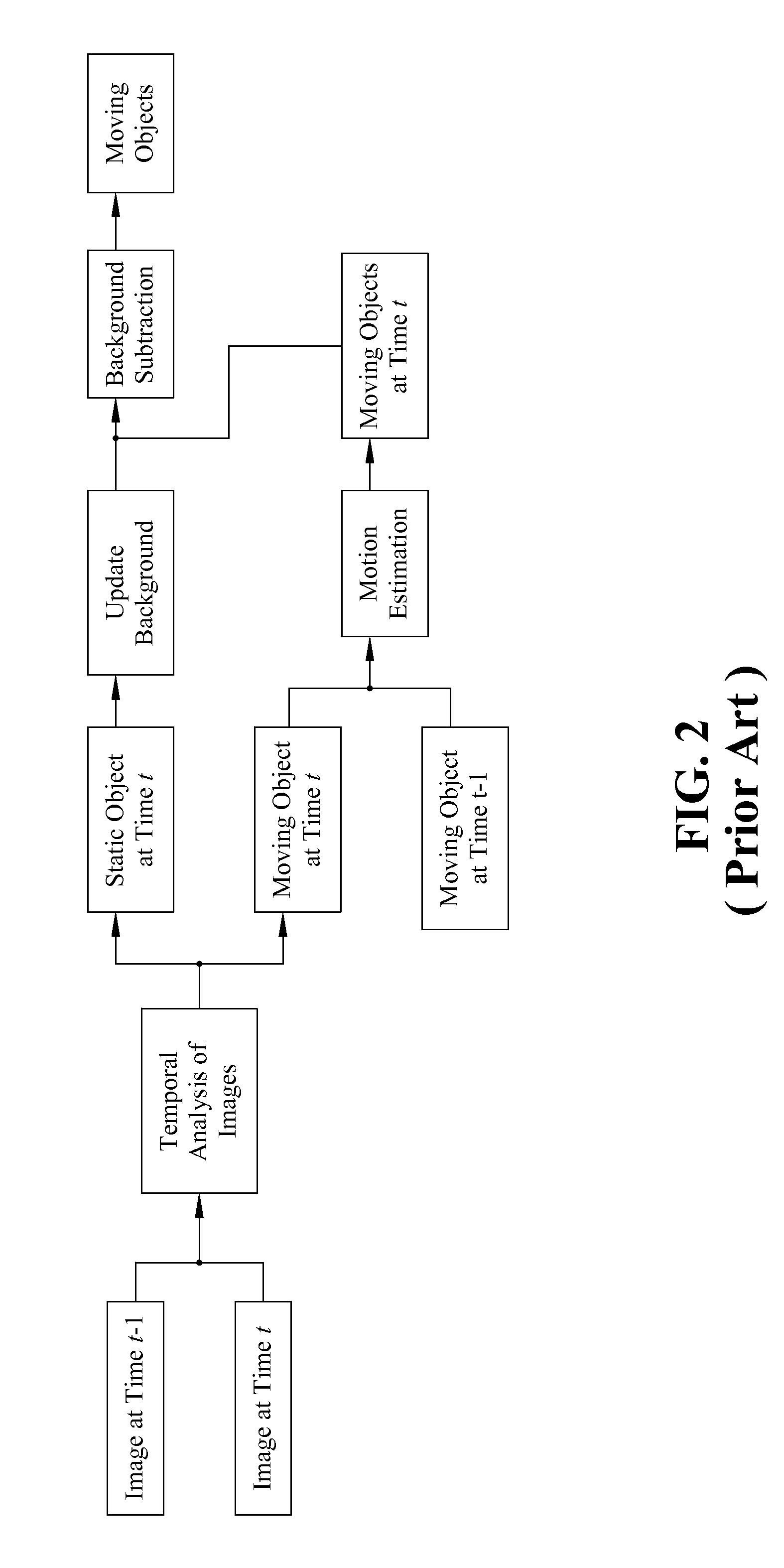
On the other hand, for movable camera surveillance, the movement of the camera will cause the entire image change and the compensation to the error caused by the camera movement makes it difficult to use a single image-based technique to effectively detect moving objects.
Therefore, only the outer profile of moving objects can be detected, while the inner area of the entire moving objects cannot be detected.

Method used


Image

  • Moving object detection apparatus and method
  • Moving object detection apparatus and method
  • Moving object detection apparatus and method

Examples


Embodiment Construction

[0021]In the disclosed exemplary embodiments of the present invention, the images captured by the movable camera are first compensated by the image analysis for the background changed caused by the camera movement. Then, the temporal differencing, distance transformation, and background subtraction techniques are combined to detect the moving object regions in a stable manner.

[0022]FIG. 3 shows a schematic view of an exemplary moving object detection apparatus, consistent with certain disclosed embodiments. Referring to FIG. 3, the exemplary moving object detection apparatus 300 may comprise an image capture module 301, an image alignment module 303, a temporal differencing module 305, a distance transform module 307, and a background subtraction module 309.

[0023]Image capture module 301 captures images for moving objects 310 at different times. If image capture module 301 is on a movable platform, image align module 303 aligns the images captured at different times. The aligned ima...


PUM


Abstract

Disclosed is directed to a moving object detection apparatus and method. The apparatus comprises an image capture module, an image alignment module, a temporal differencing module, a distance transform module, and a background subtraction module. The image capture module derives a plurality of images in a time series. The image alignment module aligns the images if the image capture module is situated on a movable platform. The temporal differencing module performs temporal differencing on the captured images or the aligned images, and generates a difference image. The distance transform module transforms the difference image into a distance map. The background subtraction module applies the distance map to background subtraction technology and compares the results with the current captured image, so as to obtain the information for moving objects.

Description

FIELD OF THE INVENTION[0001]The present invention generally relates to a moving object detection apparatus and method.BACKGROUND OF THE INVENTION[0002]Moving object detection plays an important role in automatic surveillance systems. Surveillance systems detect abnormal security events by analyzing the trajectory and behavior of moving objects in an image, and notify the related security staff. The development of the security robots moves towards the intelligent security robots with abnormal event detection capability to support dynamic deployment and repetitive, continuous surveillance. The moving object detection aims to replace the passive recording widely used in conventional surveillance systems.[0003]For example, US. Pat. No. 6,867,799 disclosed a method and apparatus for object surveillance with a movable camera, including the construction of a surveillance mechanism of maintaining a moving object of interest within the filed of view of a movable camera in an object surveilla...

Claims


Application Information

Patent Timeline
Patent Type & Authority Patents(United States)
IPC IPC(8): G06K9/00
CPCG06T7/2053G06T2207/10016G06T2207/30232G06T7/254
Inventor SHIH, MING-YUCHAO, YING-YING
Owner IND TECH RES INST
Learn More