Solid-state imaging device and its manufacturing method
a technology of solid-state imaging and manufacturing methods, which is applied in the direction of instruments, television systems, lenses, etc., can solve the problems of deteriorating image quality, smear, and more likely leakage of electric charge into the charge transfer unit, so as to prevent smear and improve image quality. , the effect of high reliability
- Summary
- Abstract
- Description
- Claims
- Application Information
AI Technical Summary
Benefits of technology
Problems solved by technology
Method used
Image
Examples
first embodiment
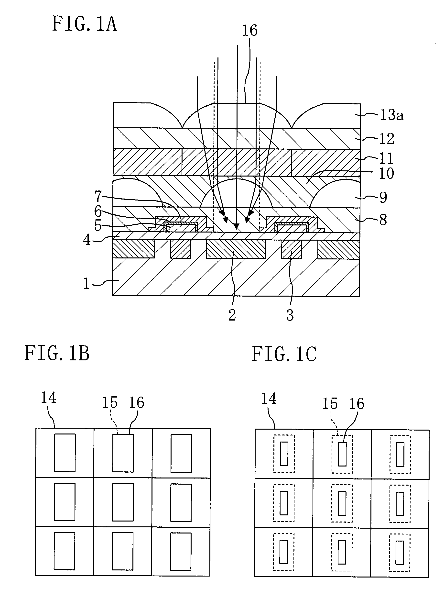
[0050]FIG. 1A is a cross-sectional view showing a configuration of a solid-state imaging device according to this embodiment. As shown in FIG. 1A, the solid-state imaging device of this embodiment includes: a semiconductor substrate 1 made of silicon or the like; a photoelectric conversion region (photoelectric conversion device region) 2 and a transfer channel region 3 provided in the semiconductor substrate 1; a first insulating film 4 provided on an entire surface of the semiconductor substrate 1; a transfer electrode 5 provided on the transfer channel region 3 with the first insulating film 4 being interposed therebetween; a second insulating film 6 covering a side surface and an upper surface of the transfer electrode 5; a light shield film 7 provided on the first insulating film 4, extending over a side surface and an upper surface of the second insulating film 6, and having an opening portion directly above the photoelectric conversion region 2; a first planarization layer 8 ...
second embodiment
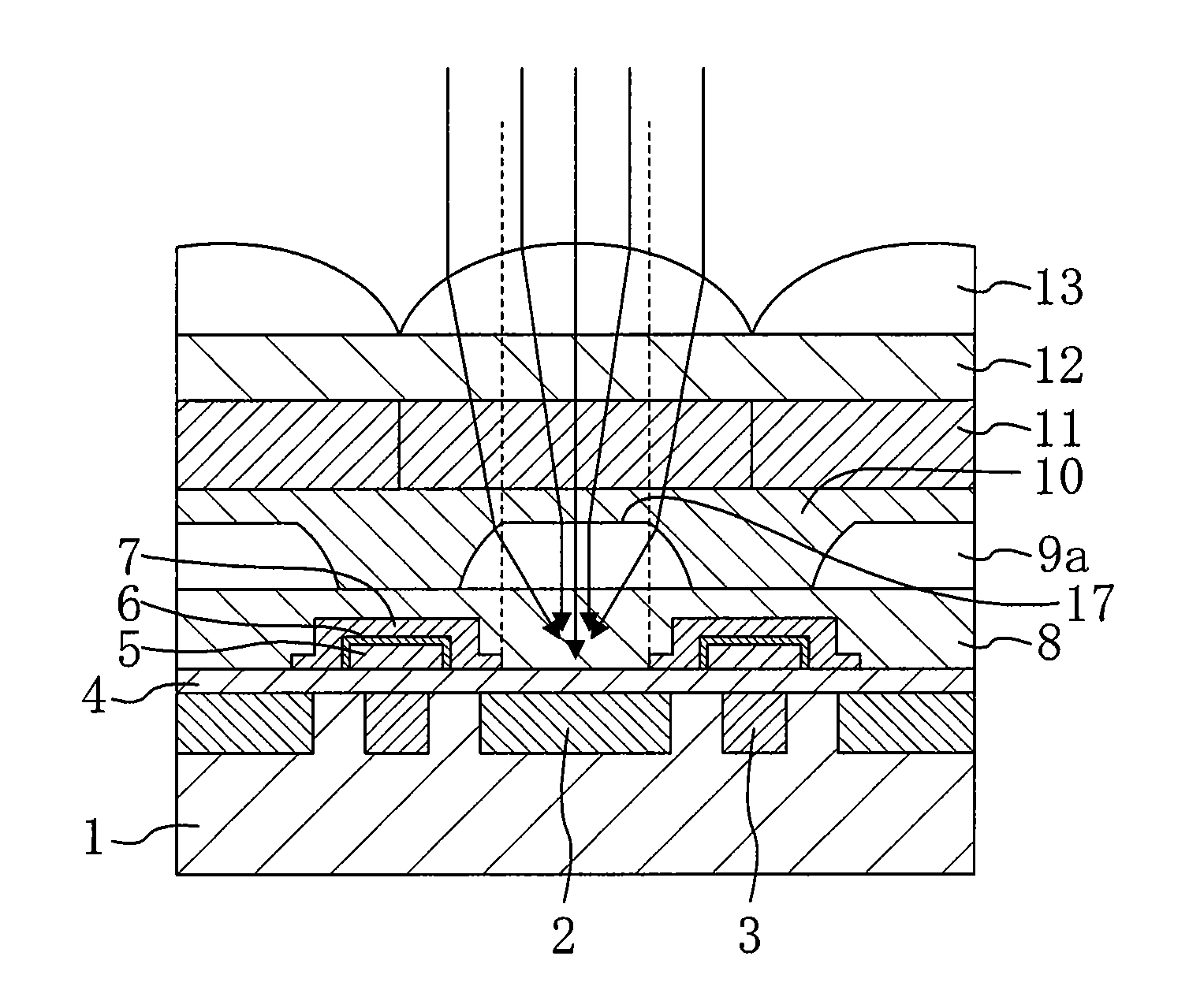
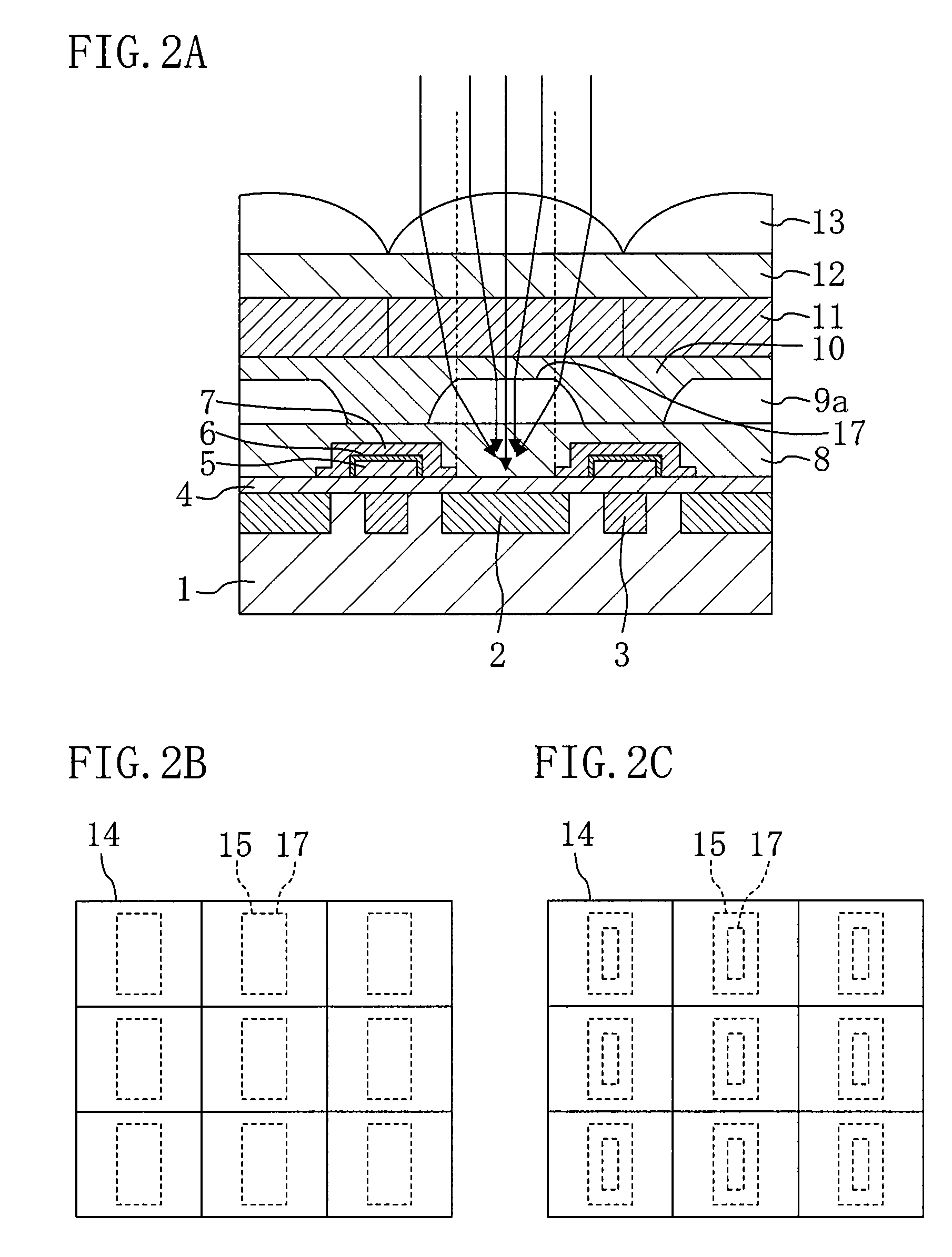
[0056]FIG. 2A is a cross-sectional view showing a configuration of a solid-state imaging device according to a second embodiment of the present invention. Note that the solid-state imaging device of this embodiment is different from that of the first embodiment in only a portion of the configuration. Therefore, the same parts as those of the first embodiment are indicated by the same reference symbols and will not be described.
[0057]As shown in FIG. 2A, in the solid-state imaging device of this embodiment, a first microlens 9a and a second microlens 13 each have an upward-convex upper surface. The first microlens 9a has, at a top portion thereof, a flat surface 17 positioned directly above a photoelectric conversion region 2. The flat surface 17 is formed in parallel with a surface of a semiconductor substrate 1. The flat surface 17 will be described in greater detail with reference to FIG. 2B. Note that the solid-state imaging device of this embodiment has a configuration similar t...
third embodiment
[0062]FIG. 3A is a cross-sectional view showing a configuration of a solid-state imaging device according to a third embodiment of the present invention. Note that the solid-state imaging device of this embodiment is different from that of the first embodiment in only a portion of the configuration. Therefore, the same parts as those of the first embodiment are indicated by the same reference symbols and will not be described.
[0063]As shown in FIG. 3A, in the solid-state imaging device of this embodiment, a first microlens 9a and a second microlens 13a each have an upward-convex upper surface. The first and second microlenses 9a and 13a also have, at respective top portions thereof, respective flat surfaces 17 and 16 positioned directly above a photoelectric conversion region 2. The flat surfaces 17 and 16 are formed in parallel with a surface of a semiconductor substrate 1. The flat surfaces 17 and 16 will be described in greater detail with reference to FIG. 3B. Note that the soli...
PUM
 Abstract
Description
Claims
Application Information
 - R&D
- Intellectual Property
- Life Sciences
- Materials
- Tech Scout
- Unparalleled Data Quality
- Higher Quality Content
- 60% Fewer Hallucinations
Browse by: Latest US Patents, China's latest patents, Technical Efficacy Thesaurus, Application Domain, Technology Topic, Popular Technical Reports.
© 2025 PatSnap. All rights reserved.Legal|Privacy policy|Modern Slavery Act Transparency Statement|Sitemap|About US| Contact US: help@patsnap.com


