
Method of processing a digitized workpiece, particularly a three-dimensional model of a dental prosthetic item to be produced therefrom, and apparatus therefor

a three-dimensional model and workpiece technology, applied in the field of three-dimensional models of dental prosthetic items, can solve the problems of only insufficient and indirect influence of the surface between the lines or points by users, and achieve the effect of enlarge or diminishing the action zon

Active Publication Date: 2011-07-19
SIRONA DENTAL SYSTEMS
View PDF12 Cites 48 Cited by
  • Summary
  • Abstract
  • Description
  • Claims
  • Application Information

AI Technical Summary

Benefits of technology

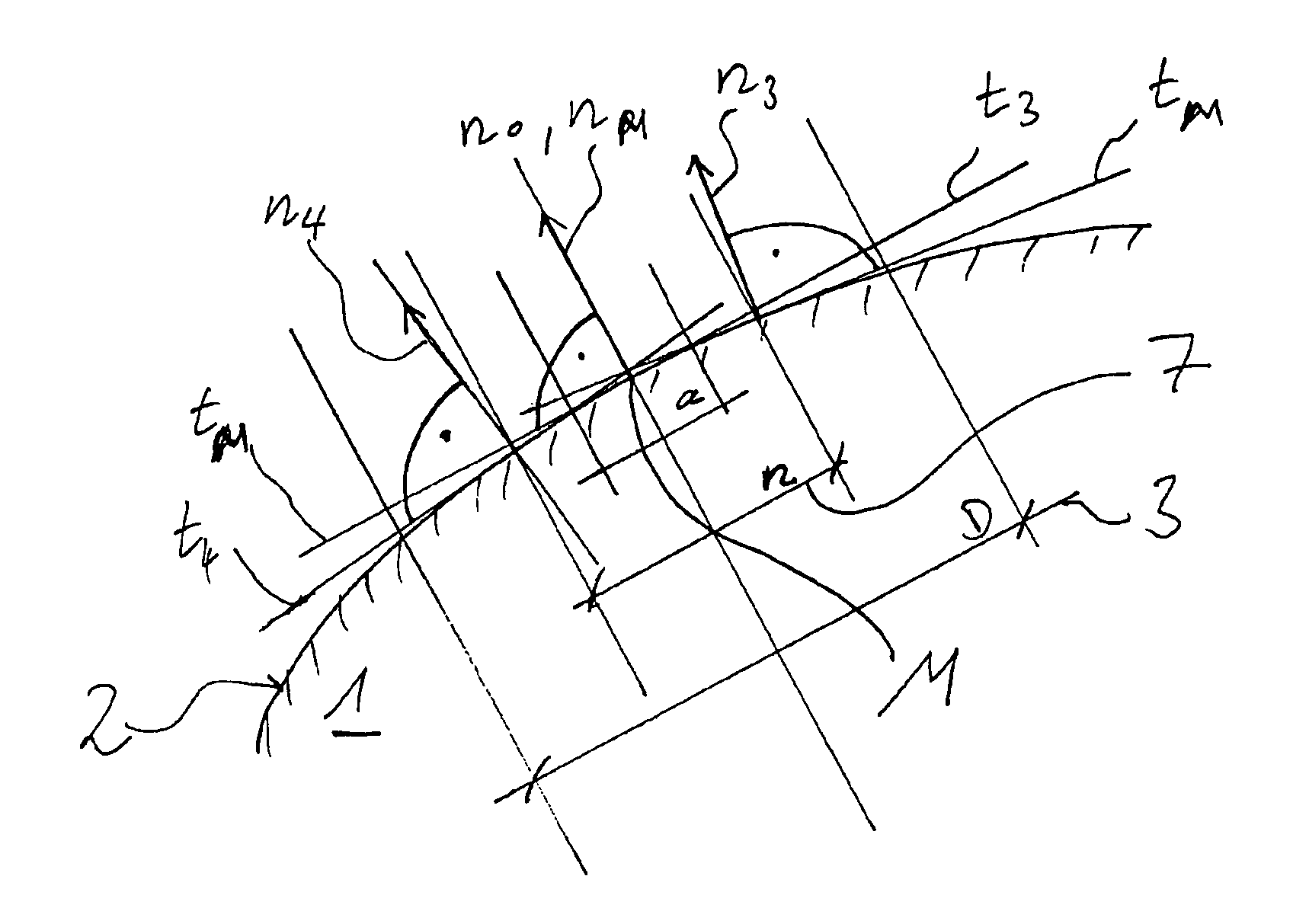
[0012]The tool proposed herein enables the user to apply or remove a thin layer of material of substantially constant layer thickness (hereafter referred to as a “change in height”) at an arbitrary point on the surface. The size of the region is adjustable. By using a repeat function when moving the tool over the same place on the surface, the user can build up and / or clear away tooth structures in a simple way, without obliterating the fine structural features.
[0013]By decoupling from the paradigm of conventional dental techniques, new possibilities for the design of dental prosthetic items arise. The user can effect better control of the change in shape than with currently available tools whilst retaining existing fine structural features.
[0014]The ratio of the change in height in the zone of action to the extent of the zone of action is at most 1:50, and preferably between 1:100 and 1:200. It is advantageous for the ratio of the thickness of the change in height to the extent of the zone of action to be 1:140. This allows for sufficiently fine processing without destroying fine structural features.
[0015]It is advantageous for the ratio of the width of the transition region of the zone of action to the change in height to be between 1:1 and 20:1. This allows for a sufficiently smooth transition.
[0022]It may be advantageous to visibly distinguish the region already processed by the tool from the representation of the surface of the model. The user will thus know which region of the surface has already been processed. Furthermore, frequently processed surfaces can be shown differently from once processed surfaces, for example by colored hatching.

Problems solved by technology

The line-based or point-based tools are usually easy to use, but they have the disadvantage that the user can only insufficiently and indirectly influence the surface between the lines or points.

Method used


Image

  • Method of processing a digitized workpiece, particularly a three-dimensional model of a dental prosthetic item to be produced therefrom, and apparatus therefor
  • Method of processing a digitized workpiece, particularly a three-dimensional model of a dental prosthetic item to be produced therefrom, and apparatus therefor
  • Method of processing a digitized workpiece, particularly a three-dimensional model of a dental prosthetic item to be produced therefrom, and apparatus therefor

Examples


Embodiment Construction

[0040]FIG. 1 shows a digitized workpiece in the form of a three-dimensional model of a dental prosthetic item for production therefrom, which is to be altered by the user. The model is shown on the monitor of a computer.

[0041]During processing, the surface 2 of the model of the dental prosthetic item, present in the form of digital data, will be processed by a tool which influences the design, ie, influences these data. The tool acts on a local zone of action 3 on the surface 2. The zone of action 3 is shown as a circle, but can have other suitable shapes.

[0042]Input means, not shown in the figure, are provided for moving the zone of action 3 of the tool over surface 2. Examples thereof are a computer mouse or a digital pen plotter which controls a cursor 11 or 12. The tool is initially free to move over the surface of the representation and can be activated as needed. This happens for example by a mouse-click at a particular place or by clicking and holding a mouse button while at ...


PUM


Abstract

In a method of processing a digitized workpiece (1), especially a three-dimensional model of a dental prosthetic item to be produced therefrom, by altering the surface data of the workpiece by means of a tool which acts on a local zone of action (3) on the surface (2), a change in height of said surface (2) is effected in said zone of action (3) of said tool when the tool is applied to said surface, the said zone of action of said tool covering a modified region (5) showing a substantially constant change in height (t) over the zone of action (3) and also a transition region (4), in which the surface of the modified region (5) merges into the surface surrounding said zone of action (3).

Description

BACKGROUND OF THE INVENTION[0001]1. Field of the Invention[0002]The invention relates to a method of processing a digitized workpiece, particularly a three-dimensional model of a dental prosthetic item to be produced therefrom, by altering the surface data of the workpiece by means of a tool which acts on a local zone of action on the surface.[0003]A design being processed by CAD is not constrained by the limitations of the physical characteristics of materials and tools, indeed, the operation of the tool can completely free itself from these characteristics and overcome their disadvantages. It is desired, in particular, to improve the operability thereof.[0004]Existing dental CAD / CAM systems offer no free-form tools that go beyond the techniques used in conventional dental technology. Thus these free-form tools, like those used in manual processing of physical models, have the disadvantage that the fine structures of the surface are obliterated due to the application of wax.[0005]2...

Claims


Application Information

Patent Timeline
Patent Type & Authority Patents(United States)
IPC IPC(8): G06T15/00G09G5/00
CPCA61C13/0004
Inventor ORTH, ULRICHWEDLER, VOLKER
Owner SIRONA DENTAL SYSTEMS
Learn More