Imaging apparatus

a technology of a sonic sonic and a trigger is applied in the field of sonic sonic devices, which can solve the problems of difficult to make the package completely light-tight, the image pixels are not optimised for rapid x-ray triggering, and the x-ray triggering is not optimised for rapid triggering, so as to achieve high signal voltage, high reliability of triggers, and high discrimination of signals from noise in 1 ms sample time.

Inactive Publication Date: 2011-07-12
E2V TECH (UK) LTD
View PDF11 Cites 3 Cited by
  • Summary
  • Abstract
  • Description
  • Claims
  • Application Information

AI Technical Summary

Benefits of technology

[0012]Conveniently, the trigger pixel has a substantially higher signal voltage per unit x-ray dose than any one of the array of imaging pixels, such that a single x-ray photon incident on the trigger pixel gives a signal substantially above a pixel read noise and such that relatively few incident x-ray photons saturate the trigger pixel, so that discrimination of a signal from noise in a 1 ms sample time is high, and the reliability of trigger is high.

Problems solved by technology

A problem with this approach is that the imaging pixels are not optimised for rapid triggering and are sensitive to stray light.
The event detector cells are triggered by light from a scintillator, which also provides light to the imaging cells, and are therefore not optimised for rapid x-ray triggering and are sensitive to stray light.
It is therefore difficult to make the package completely light-tight and false triggering may occur.
In principle it would be possible to average the voltage across each pixel but it is desirable to integrate the trigger mechanism in the sensor device and an averaging function requires too much logic to be readily integrated.

Method used


Image

  • Imaging apparatus
  • Imaging apparatus
  • Imaging apparatus

Examples


Embodiment Construction

[0039]Throughout the description, identical reference numerals are used to identify like parts.

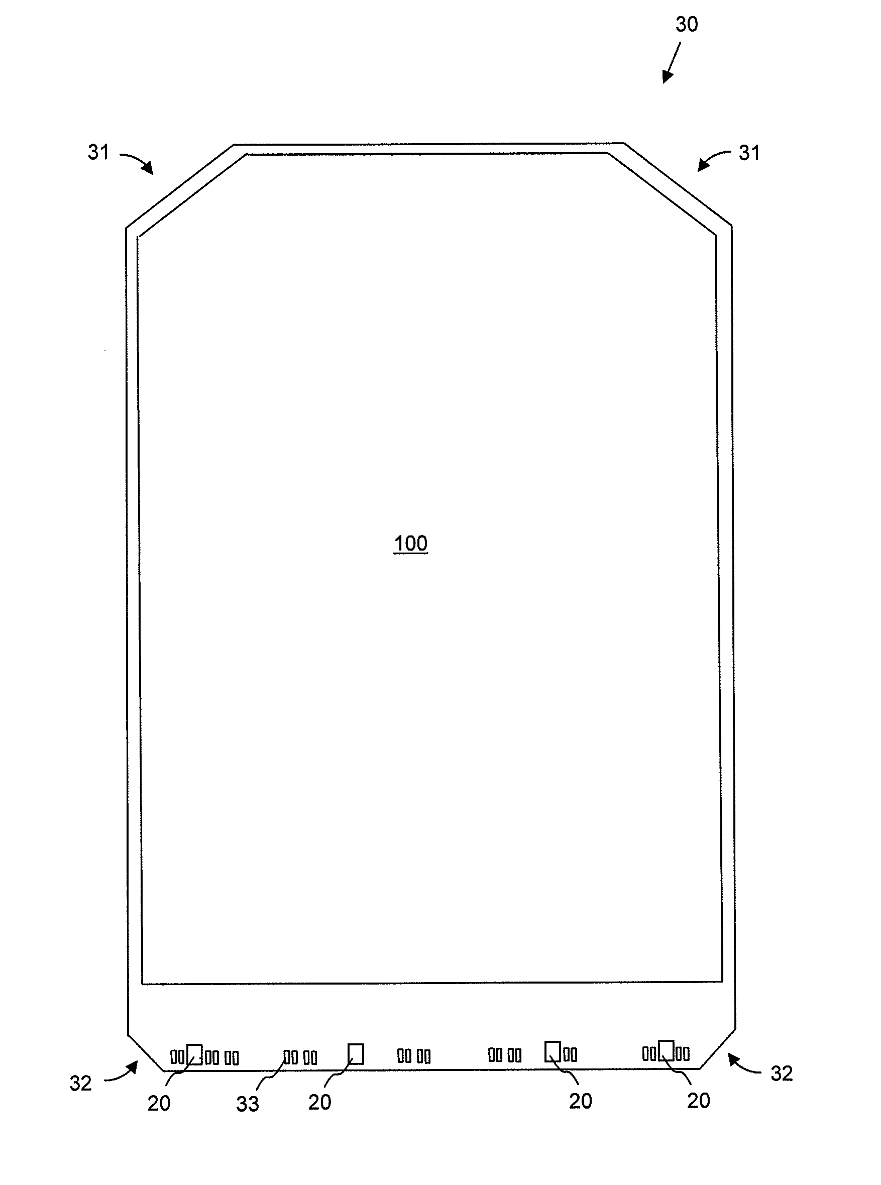
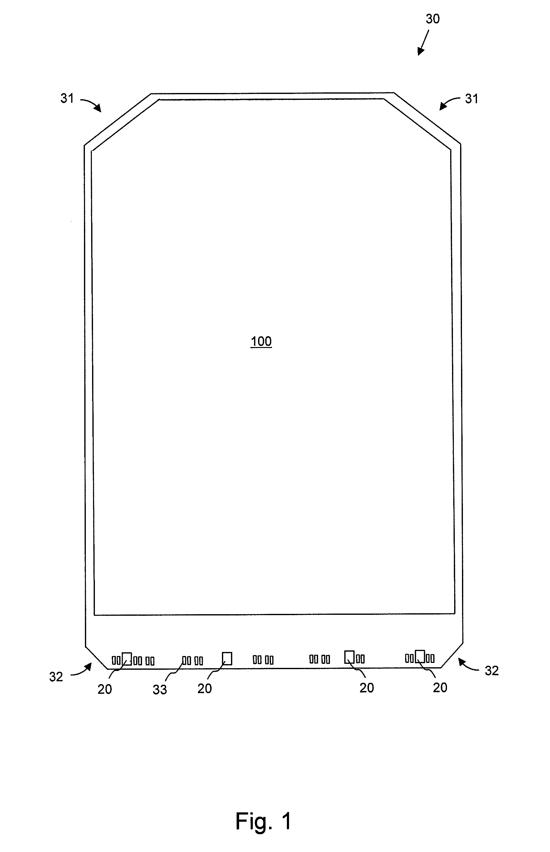
[0040]Referring to FIGS. 1 and 4, an x-ray sensor according to the invention comprises an array 100 of imaging pixels 10, overlaid by a scintillator 41 and optionally a fibre optic plate 42, on a substrate 30 which has substantially 45 deg. chamfered corners 31 at a first end of the substrate and substantially 45 deg. chamfered corners 32, smaller than the first chamfered corners 31, at a second end to provide a more comfortable shape in a patient's mouth than a purely rectilinear shape. The second end of the substrate is provided with electrical connection pads 33. Four spaced-apart peripheral trigger pixels arrays 20 are interspersed between the connection pads 33. As best seen in FIG. 5, the peripheral trigger pixels arrays 20 are therefore not covered by the scintillator 41 but are covered instead by a layer 51 impervious to visible light but substantially transparent to x-rays, such a...


PUM


Abstract

An imaging apparatus for x-rays includes a scintillator, overlying an array of imaging pixels on a substrate, and at least one trigger pixel array externally peripheral to the array of imaging pixels on the substrate such that the trigger pixel array is not substantially overshadowed by the scintillator from incident x-ray radiation. A layer substantially impervious to light but transparent to x-rays overlays the trigger pixel array, such that the trigger pixels are unresponsive to light but triggered by direct hits from incident x-ray photons.

Description

CROSS-REFERENCE TO RELATED APPLICATIONS[0001]This application claims priority from GB 0701076.2 filed Jan. 19, 2007 and is derived from PCT application PCT / GB2008 / 000128 filed Jan. 16, 2008.FIELD OF THE INVENTION[0002]This invention relates to an imaging apparatus and in particular to triggering an x-ray imager.BACKGROUND OF THE INVENTION[0003]Solid-state x-ray imagers using CCD or CMOS devices for dental and other medical applications are well known. Typically, x-ray sensors such as intra-oral dental sensors include a scintillator to convert x-ray photons from the x-ray source into light, which is then imaged by the sensor.[0004]Usually there is no direct connection between a source of x-rays and the imaging apparatus irradiated by the x-rays passing from the x-ray source through or past an object to be imaged by which imaging may be initiated at a beginning of an x-ray exposure. Synchronization of image capture with x-ray emission may therefore be by a trigger mechanism within the...

Claims


Application Information

Patent Timeline
Patent Type & Authority Patents(United States)
IPC IPC(8): G01T1/20
CPCG01T1/2018G01T1/20184G01T1/20185A61B6/00G01T1/20
Inventor MOODY, IANFRYER, MARTIN
Owner E2V TECH (UK) LTD
Why Eureka
Try Eureka