
Centrifuge tube for separating and aspirating biological components

a technology of centrifuge tube and biological components, which is applied in the field of centrifuge tube, can solve the problems of high cost, high production cost, and inconvenient use of apparatus, and achieve the effect of simple, high-reliability, and high-efficiency

Active Publication Date: 2011-07-12
EMCYTE CORP
View PDF10 Cites 31 Cited by
  • Summary
  • Abstract
  • Description
  • Claims
  • Application Information

AI Technical Summary

Benefits of technology

[0007]It is therefore an object of the present invention to provide a simpler, more efficient and yet highly reliable centrifuge tube that enables blood and other biological products to be separated into constituent components and aspirated following separation.
[0008]It is a further object of this invention to provide a centrifuge tube with aspirating capabilities that is manufactured much less intricately and far less expensively than existing devices of this type.
[0010]It is a further object of this invention to provide a centrifuge tube that permits a host of chemicals, bodily fluids and other biological products to be separated and individually aspirated with minimal cross-contamination.
[0011]It is a further object of this invention to provide a centrifuge tube that is particularly effective for sequestering a high concentration of platelet-rich plasma for use in various medical, surgical and veterinary procedures.
[0012]It is a further object of this invention to provide an aspirating centrifuge tube that may be used effectively for separating and aspirating a wide range of biological products, including but limited to blood, stem cells, bone marrow aspirate, etc.
[0013]It is a further object of this invention to provide a centrifuge tube that may be used effectively in various medical and veterinary applications.

Problems solved by technology

Conventional aspiration techniques often fail to provide a satisfactory concentration of platelets.
Cross-contamination between the constituent products is frequently encountered.
This apparatus is fairly intricate and thus quite expensive and complicated to manufacture.

Method used


Image

  • Centrifuge tube for separating and aspirating biological components
  • Centrifuge tube for separating and aspirating biological components
  • Centrifuge tube for separating and aspirating biological components

Examples


Embodiment Construction

[0018]Other objects, features and advantages will occur from the following description of a preferred embodiment and the accompanying drawings, in which:

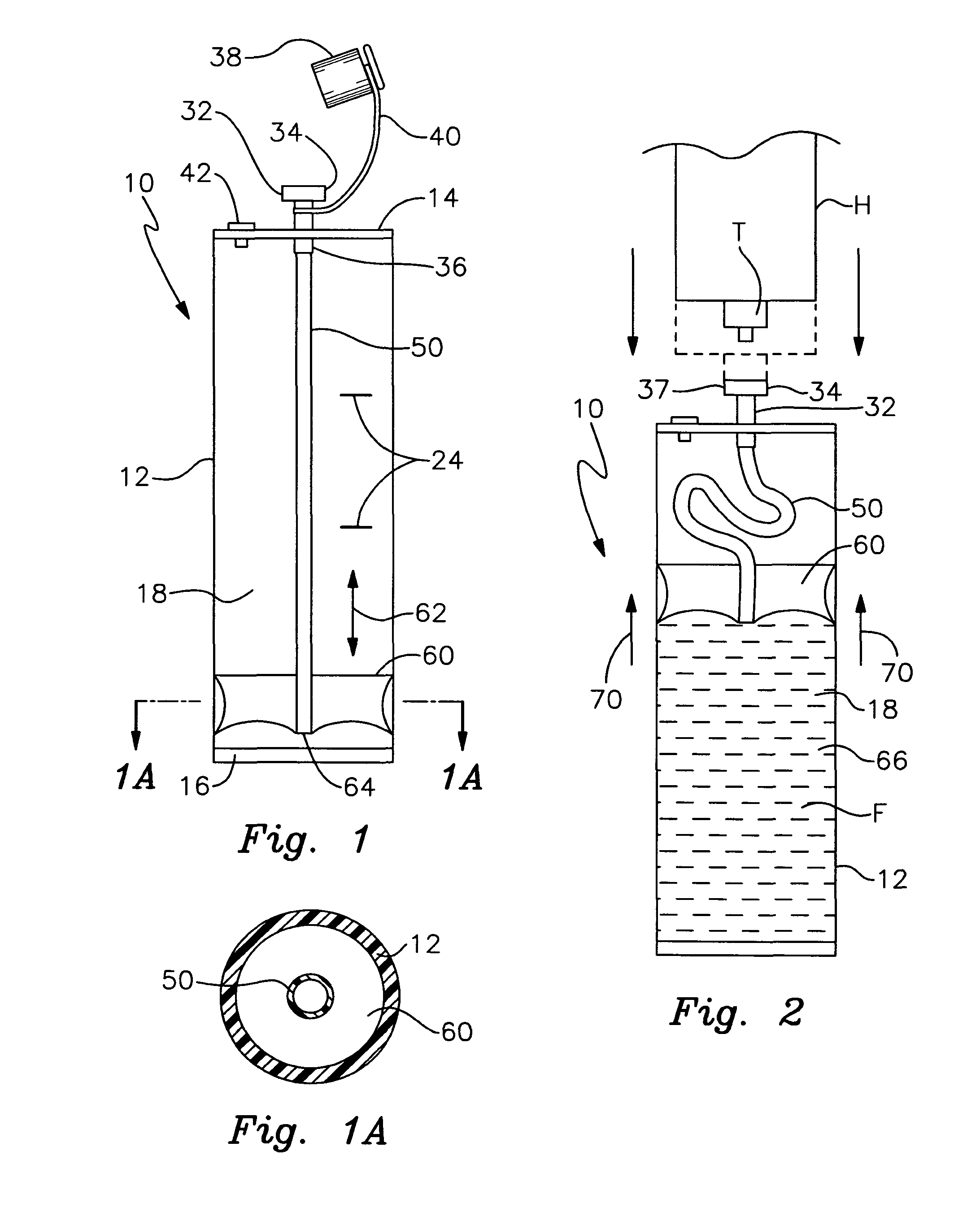
[0019]FIG. 1 is an elevational cross sectional view of the centrifuge tube assembly of this invention without any fluid or other biological product within the tubular receptacle;

[0020]FIG. 1A is a cross sectional view taken along line 1A-1A of FIG. 1;

[0021]FIG. 2 is a view similar to FIG. 1 with a hypodermic needle positioned above the tube and with a biological fluid to be separated introduced into the tubular receptacle;

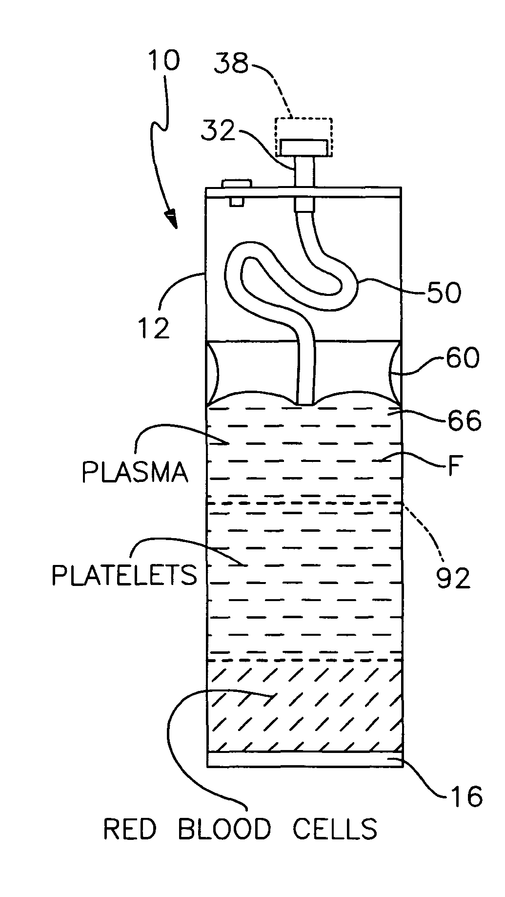
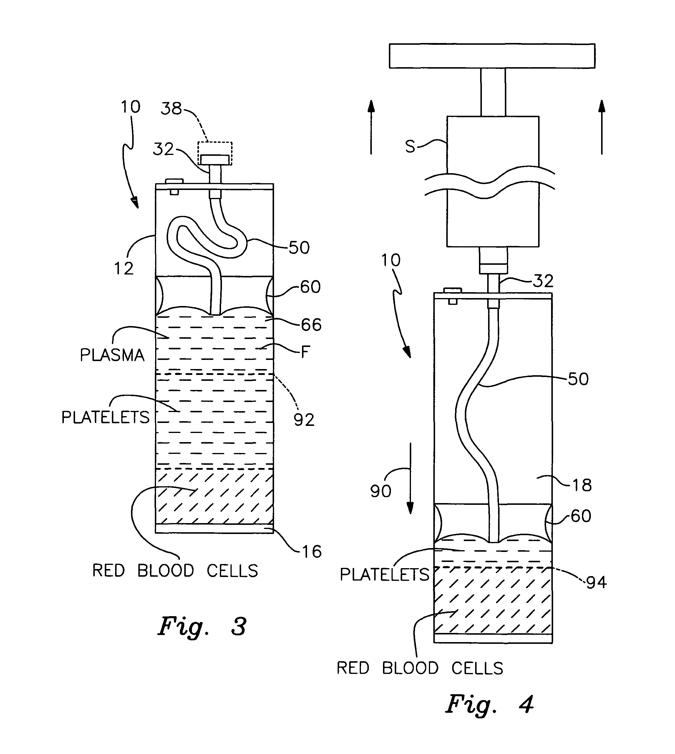
[0022]FIG. 3 is a view similar to FIGS. 1 and 2, wherein the tube assembly has been centrifuged to separate the fluid in the tube into three constituent components; and

[0023]FIG. 4 is a view similar to FIGS. 1-3 wherein a hypodermic needled engaged with the tube is being operated to aspirate successive constituent components of the biological product from the tube.

[0024]There is shown in FIG. 1 a centrifuge tube as...


PUM


Abstract

A centrifuge tube assembly includes an elongate tubular receptacle having a capped upper end. The capped upper end includes a single inlet / outlet port formed therethrough for communication with an interior of the tubular receptacle. A flexible aspiration pipe is communicably engaged with the inlet / outlet port for extending longitudinally through the cylindrical receptacle. A sealing diaphragm is attached to a distal end of the pipe. The diaphragm is longitudinally movable within the tubular receptacle and sealably interengages an interior wall of the receptacle. Biological products are introduced into and aspirated from the receptacle below the diaphragm by the fluid conducting pipe.

Description

RELATED APPLICATION[0001]This application claims the benefit of U.S. Provisional Patent Application Ser. No. 61 / 133,893 filed Jul. 3, 2008.FIELD OF THE INVENTION[0002]This invention relates to a centrifuge tube, which enables biological products such as blood, stem cells, bone marrow aspirate and the like to be separated into constituent components, and aspirated after the biological product has been centrifuged. The apparatus is particularly effective for sequestering platelet-rich plasma for use in surgical, medical and veterinary procedures.BACKGROUND OF THE INVENTION[0003]Platelet-rich blood plasma is required for use in various medical procedures. This blood product is particularly effective due to its growth promoting features, which assist greatly in wound healing and bone regeneration. Presently, blood plasma with a high concentration of platelets is utilized for dental implants and other periodontal procedures, facial reconstruction, oral or maxillofacial surgery and chroni...

Claims


Application Information

Patent Timeline
IPC IPC(8): B04B7/00
CPCB01L3/5021G01N21/07G01N33/491B01L2200/0684B01L2200/0689B01L2200/141B01L2300/049B01L2300/0803B01L2300/0864B01L2300/123B01L2400/0481B01L2400/049
Inventor SMITH, EMERYPENNIE, PATRICKBUZENIUS, DAVID K.
Owner EMCYTE CORP
Learn More