
Methods, systems, and devices for monitoring anisocoria and asymmetry of pupillary reaction to stimulus

a technology of anisocoria and pupillary asymmetry, applied in the field of methods, can solve the problems of few such tools presently availabl

Active Publication Date: 2011-06-28
NEUROPTICS
View PDF18 Cites 18 Cited by
  • Summary
  • Abstract
  • Description
  • Claims
  • Application Information

AI Technical Summary

Benefits of technology

Facilitates easy, quick, and accurate detection and monitoring of anisocoria and asymmetry in pupillary response, providing valuable diagnostic insights into neurological conditions by enabling real-time comparison and analysis of pupillary dynamics between the left and right pupils.

Problems solved by technology

There are, unfortunately, very few such tools presently available.

Method used


Image

  • Methods, systems, and devices for monitoring anisocoria and asymmetry of pupillary reaction to stimulus
  • Methods, systems, and devices for monitoring anisocoria and asymmetry of pupillary reaction to stimulus
  • Methods, systems, and devices for monitoring anisocoria and asymmetry of pupillary reaction to stimulus

Examples


Embodiment Construction

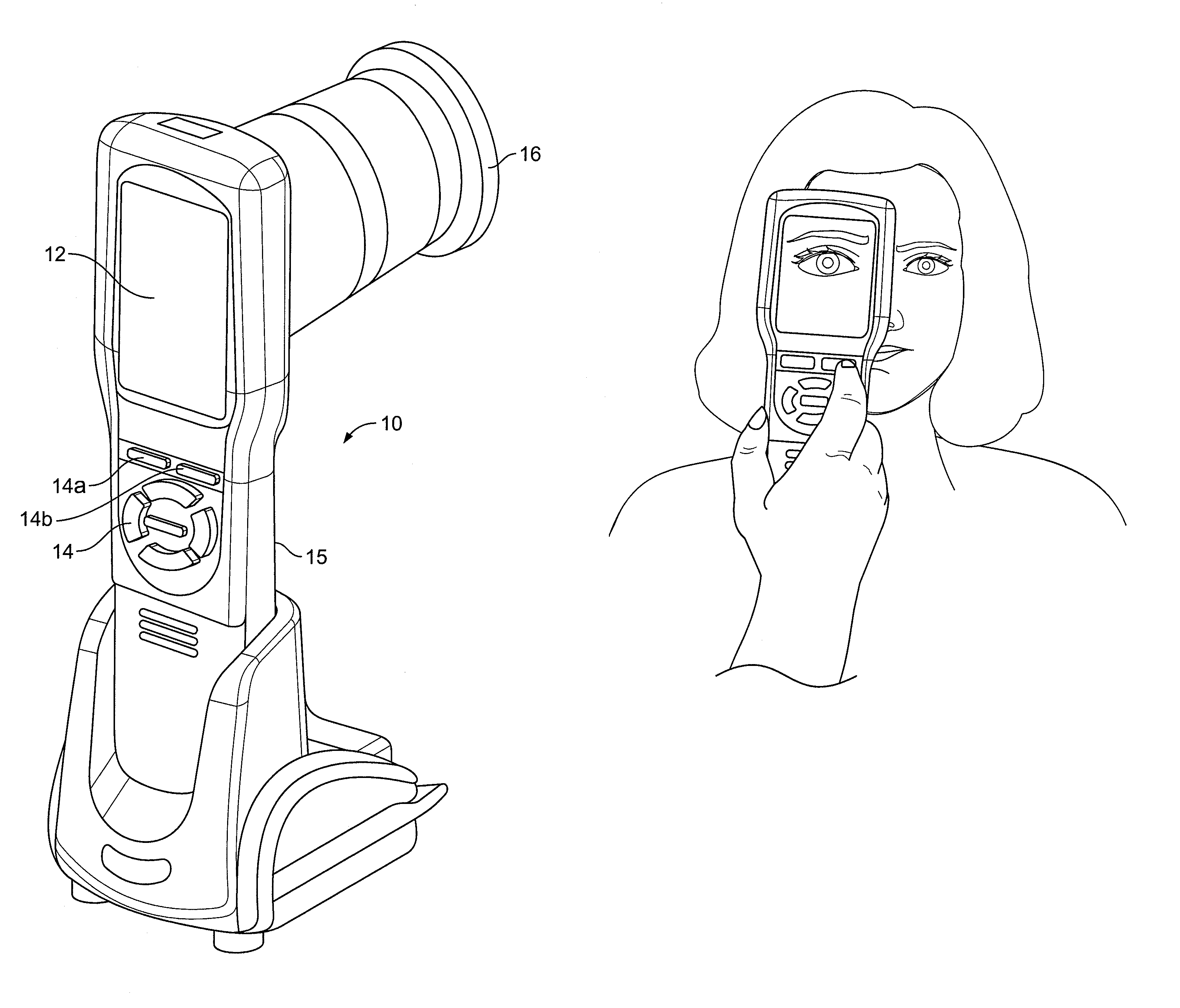
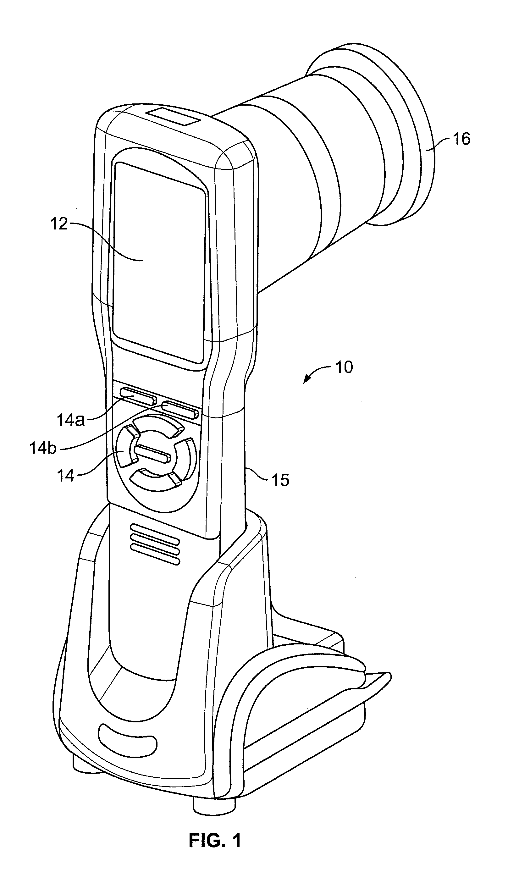
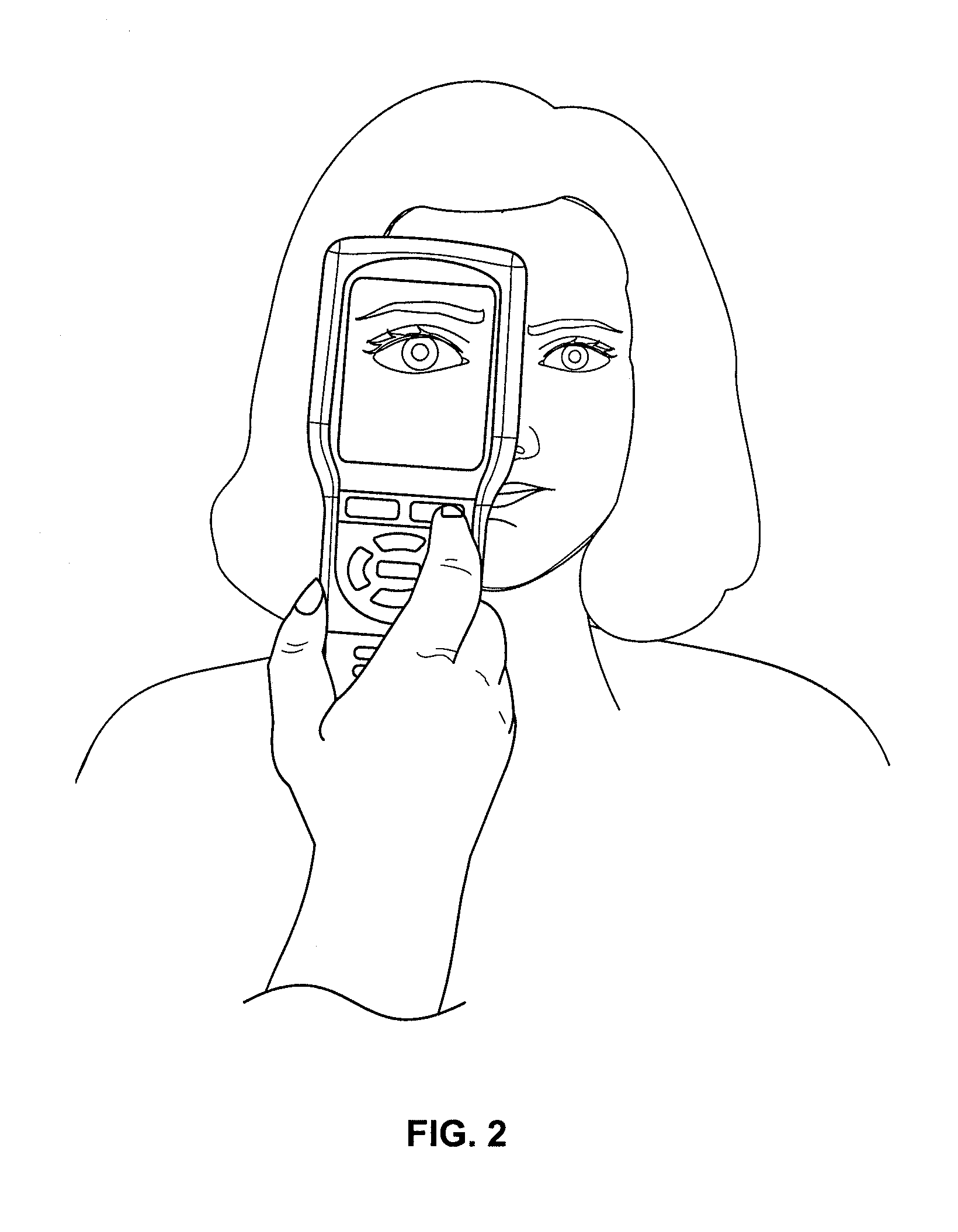
[0020]Disclosed herein is a pupillary analysis system that includes a pupillometer, such as the one shown in FIG. 1, with features that enable it to monitor and compare in real-time the response of an individual's left and right pupils to a stimulus, such as a light stimulus, auditory stimulus, or noxious stimulus. In the examples described herein the pupillometer has a light stimulus source built into it. Variations on the type of stimulus and the arrangement of that stimulus in relation to the pupillometer, such as those variations described in U.S. Pat. No. 7,147,327, are also contemplated and incorporated herein by reference. The working components, electronics, and software, other than those described below, are also fully described in, e.g., U.S. Pat. No. 7,147,327, and will therefore not be further discussed herein.

[0021]Before the present subject matter is further described, it is to be understood that the subject matter described herein is not limited to the particular embo...


PUM


Abstract

A Pupillometer is disclosed. The Pupillometer has a display, an imaging apparatus that has a pupil finder and a microprocessor, and a memory in communication with the microprocessor. The display is sized to simultaneously display a video of y or more seconds in length of a left pupil and a video of y or more seconds in length of a right pupil. The pupil finder identifies the perimeter of a pupil. The imaging apparatus is capable of recording images of an individual's pupils at a rate of x image frames per second for a period of y or more seconds and playing back said image frames as a video at x image frames per second or at another rate that is faster or slower than x image frames per second. The memory has stored therein a program for enabling said microprocessor to do the following: (i) identify a center of the left pupil and a center of the right pupil for each image frame; (ii) synchronize each image frame of the two videos starting from the first frame; (iii) cause the display to display the two videos simultaneously such that each of the image frames of the video of the left eye is synchronized to a corresponding image frame of the video of the right eye when played back on the display; and (iv) cause the two videos to be displayed so that the center of the left pupil in each image frame is aligned on the display with the center of the right pupil for the corresponding image frame.

Description

CROSS-REFERENCE TO RELATED APPLICATION[0001]This application claims the benefit of priority under 35 U.S.C. §119 to U.S. Provisional Patent Application Ser. No. 61 / 118,541, filed on Nov. 28, 2008, entitled, “METHODS, SYSTEMS, AND DEVICES FOR MONITORING ANISOCORIA AND ASYMMETRY OF PUPILLARY REACTION TO STIMULUS”, the entire disclosures of which is incorporated by reference herein.TECHNICAL FIELD OF THE DISCLOSURE[0002]The present disclosure relates to methods, systems and devices or instruments for monitoring anisocoria and asymmetry of reaction to stimulus between the left and right pupil of a subject, sometimes referred to herein as a “patient” or an “individual”. The methods and systems can be implemented through devices and instruments such as Pupillometers, which are high-tech instruments that are currently used to obtain information about a pupil's response to a stimulus. Examples of such Pupillometers are described in detail in U.S. Pat. Nos. 6,116,736, 6,260,968, 6,820,979, a...

Claims


Application Information

Patent Timeline
Patent Type & Authority Patents(United States)
IPC IPC(8): A61B9/00
CPCA61B3/112A61B3/0058A61B3/14A61B3/0025
Inventor SIMINOU, KAMRAN
Owner NEUROPTICS
Learn More