
Hinge having a damping device

Active Publication Date: 2011-06-28
JULIUS BLUM GMBH
View PDF18 Cites 42 Cited by
  • Summary
  • Abstract
  • Description
  • Claims
  • Application Information

AI Technical Summary

Benefits of technology

[0004]The object of the invention is to provide a hinge of the general kind set forth in the opening part of this specification, having a reliable damping action and a structurally simple and effective solution for appropriate restoration of the actuating element of the damping device.
[0006]The state of the art in accordance with WO 03 / 087512 A1 discloses a hinge having a damping device, wherein the damping function and the return function are effected by means of a free-wheel assembly in a common structural unit. In the course of further development of that solution, it was found that spatial separation of the damping function and the return function is advantageous. It was found that basically one single damping device for each hinge, in a suitably solid design, can be sufficient to provide an appropriate damping action. The separation of the damping function and the return function provides the advantage that the respective structural units can be designed to be more stable and more reliable and are thereby less susceptible to failure.
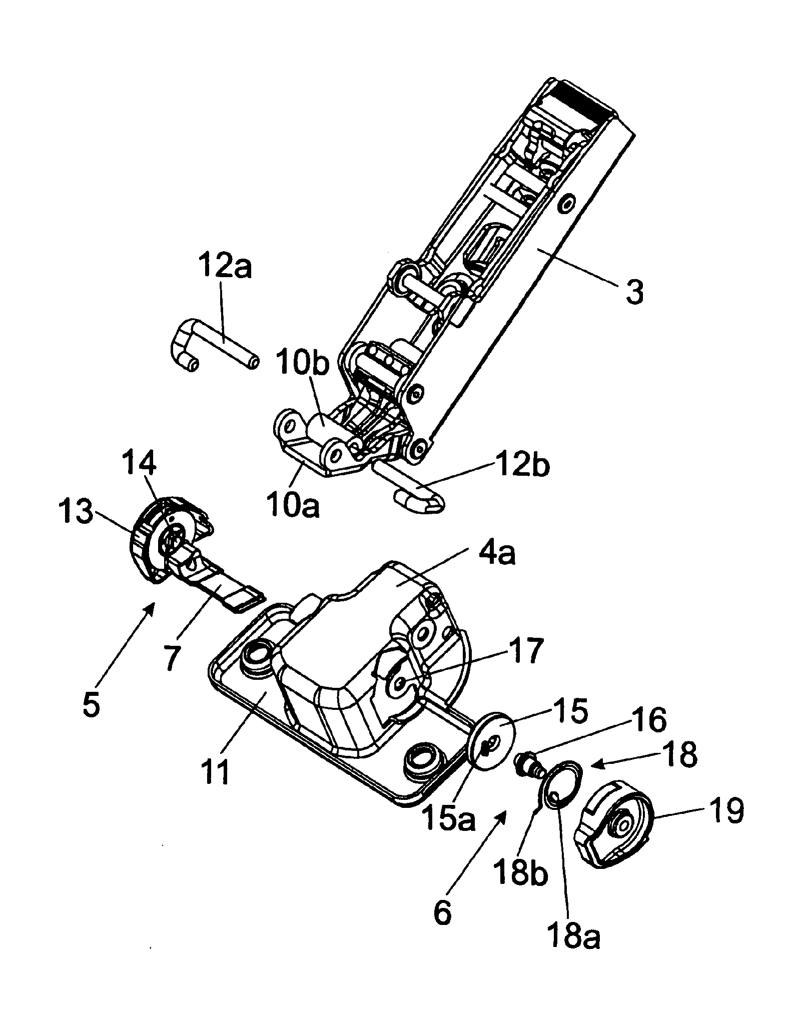
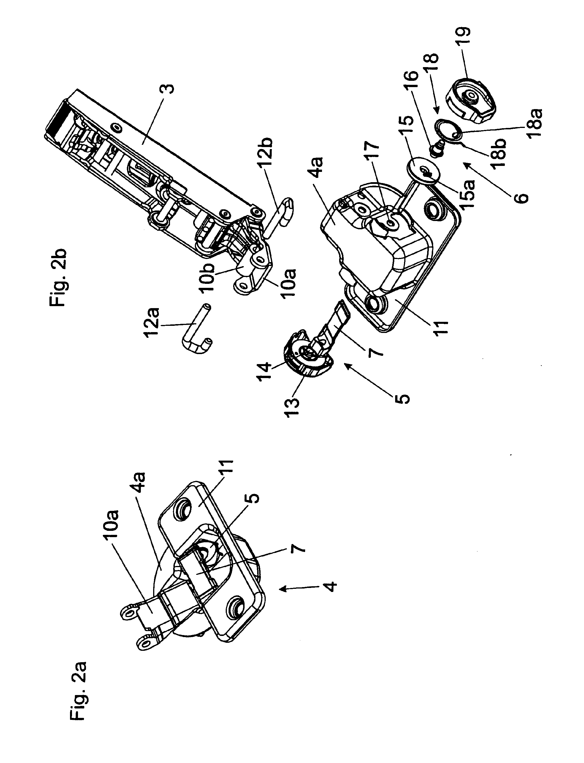
[0008]In an embodiment of the invention, the actuating element of the damping device can be connected or releasably connectable to a return element of the return mechanism. In that respect, it may be desirable if the actuating element is releasably connectable to the return element by way of a snap connection. The actuating element with the return element forms a structural unit which is inseparable during operation. In other words, a moment acting on the actuating element during the damping process is simultaneously also transmitted to the return element. Conversely, in the return stroke, a moment acting on the return element is also transmitted to the actuating element so that, after damping has occurred, the actuating element is movable again into a ready position for the next damping stroke. That configuration avoids a lateral moment on the actuating element so that one-sided loading of the actuating element can be substantially excluded.

Problems solved by technology

In general, those valve-like constructions are highly complicated and expensive in construction and manufacture and permit only very small tolerances.

Method used


Image

  • Hinge having a damping device
  • Hinge having a damping device
  • Hinge having a damping device

Examples


Embodiment Construction

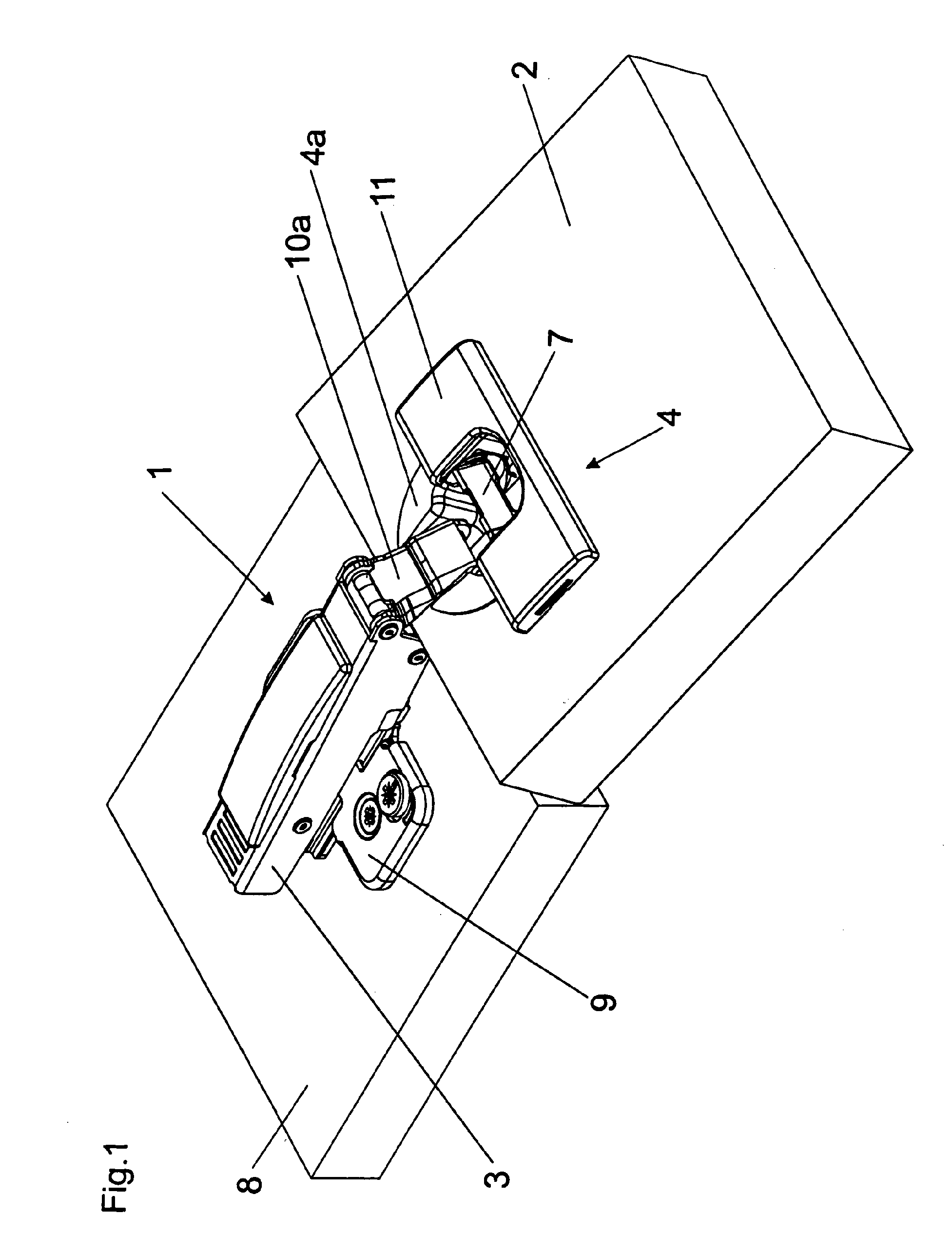
[0017]FIG. 1 shows a perspective view of a hinge identified overall by reference 1, in the mounted position. The hinge 1 includes in a conventional manner a base plate 9 which is screwed to the furniture carcass 8 and onto which a first fitment portion 3 in the form of a hinge arm can be clipped. In addition, the hinge 1 comprises an inner hinge lever 10b and an outer hinge lever 10a which connect the second fitment portion 4 with the hinge cup 4a hingedly to the stationary first fitment portion 3. The inner hinge lever 10b is concealed in the illustrated view by virtue of its cranked configuration. A bore (which cannot be seen here) into which the hinge cup 4a is sunk—as is known per se—is provided on the movable furniture portion 2. A fixing flange 11 is also provided for fastening the hinge cup 4a. Visible is an actuating element 7 which is pivotally mounted within the hinge cup 4a and which can be moved in the range of predetermined limits. An actuating mechanism includes the ou...


PUM


Abstract

A hinge, particularly for movable pieces of furniture, has at least two stop parts connected in an articulated manner (which is to say a hinge arm and a hinge cup) for fastening to pieces of furniture. The hinge has a damping device for damping the hinge movement, and has a restoring mechanism, by which an actuating element of the damping device can be moved into a starting position for the next damping stroke after damping has taken place. The damping device and the restoring mechanism are disposed as separate components on the hinge cup. The damping device, which has no restoring mechanism, is disposed on a lateral wall of the hinge cup, and the restoring mechanism is disposed on an opposing lateral wall of the hinge cup.

Description

[0001]This application is a continuation application of International application PCT / AT2009 / 000018, filed Jan. 20, 2009, the entire disclosure of which is incorporated herein by reference.BACKGROUND OF THE INVENTION[0002]The present invention relates to a hinge, in particular for movable furniture parts, comprising at least two hingedly connected fitment portions, namely a hinge arm and a hinge cup, to be fixed to furniture parts. A damping device is provided for damping the hinge movement and a return mechanism by means of which an actuating element of the damping device can be moved into a ready position for the next damping stroke. The damping device and the return mechanism are arranged as separate component units on the hinge cup.[0003]In the state of the art, it is known to provide furniture dampers with relatively complicated and expensive valve constructions in order to realize a return stroke at the end of the damping stroke so that the actuating element or the damper can ...

Claims


Application Information

Patent Timeline
IPC IPC(8): E05F1/08
CPCE05F5/006E05F5/02E05D5/08E05Y2201/21E05Y2201/256E05Y2201/266Y10T16/2771Y10T16/5383Y10T16/538Y10T16/5389E05Y2900/20E05D11/10E05F5/00
Inventor KRAMMER, BERNHARD
Owner JULIUS BLUM GMBH
Learn More