Reference signal generating configuration for an interferometric miniature grating encoder readhead using fiber optic receiver channels
a miniature grating encoder and readhead technology, applied in the field of reference signal generation configuration of miniature fiber optic encoders, to achieve the effect of high speed operation, small size and high accuracy
- Summary
- Abstract
- Description
- Claims
- Application Information
AI Technical Summary
Benefits of technology
Problems solved by technology
Method used
Image
Examples
first embodiment
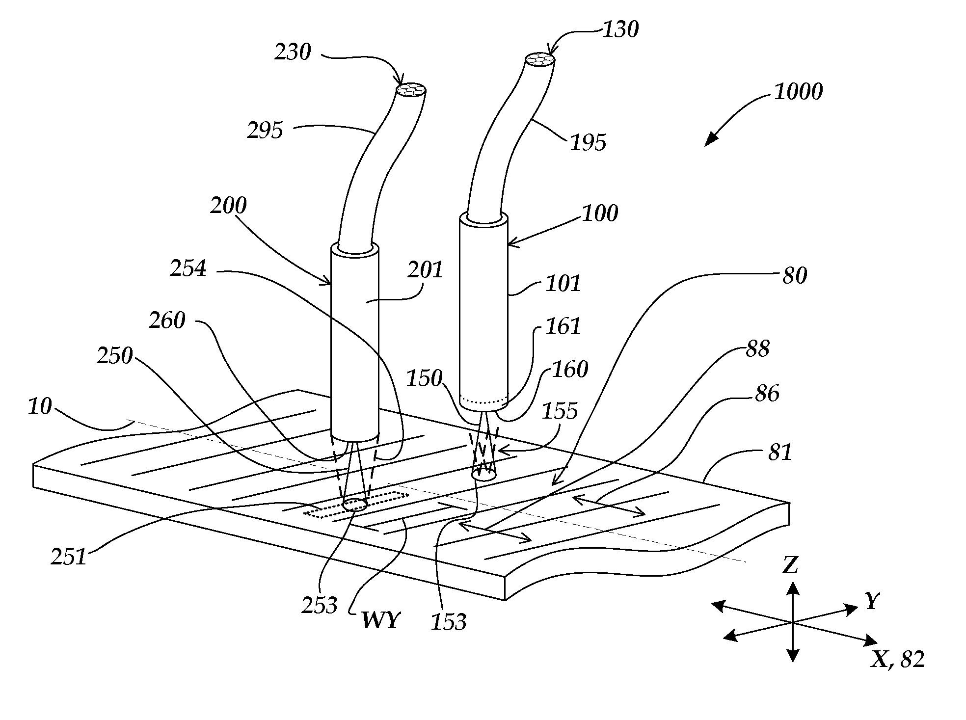
[0033]FIG. 1 is an isometric view of a miniature fiber optic readhead and scale arrangement 1000 that includes a reference signal generating configuration according to this invention. As shown in FIG. 1, the miniature fiber optic readhead and scale arrangement 1000 includes a scale member 81 that includes a scale grating 80, an incremental readhead 100, and a reference mark readhead 200. It will be appreciated the readheads 100 and 200 will generally be mounted rigidly relative to one another, or formed as a single unit, so that their displacements are synchronized.
[0034]An orthogonal XYZ coordinate system may be defined such that the y-axis is parallel to the bars of the scale grating 80, the z-axis is normal to the surface of the scale grating 80, and the x-axis is orthogonal to the y-z plane. A measuring axis 82 is parallel to the x-axis. In operation, the scale member 81 displaces along the measuring axis 82 such that the readhead 100 is displaced along an incremental measuring ...
second embodiment
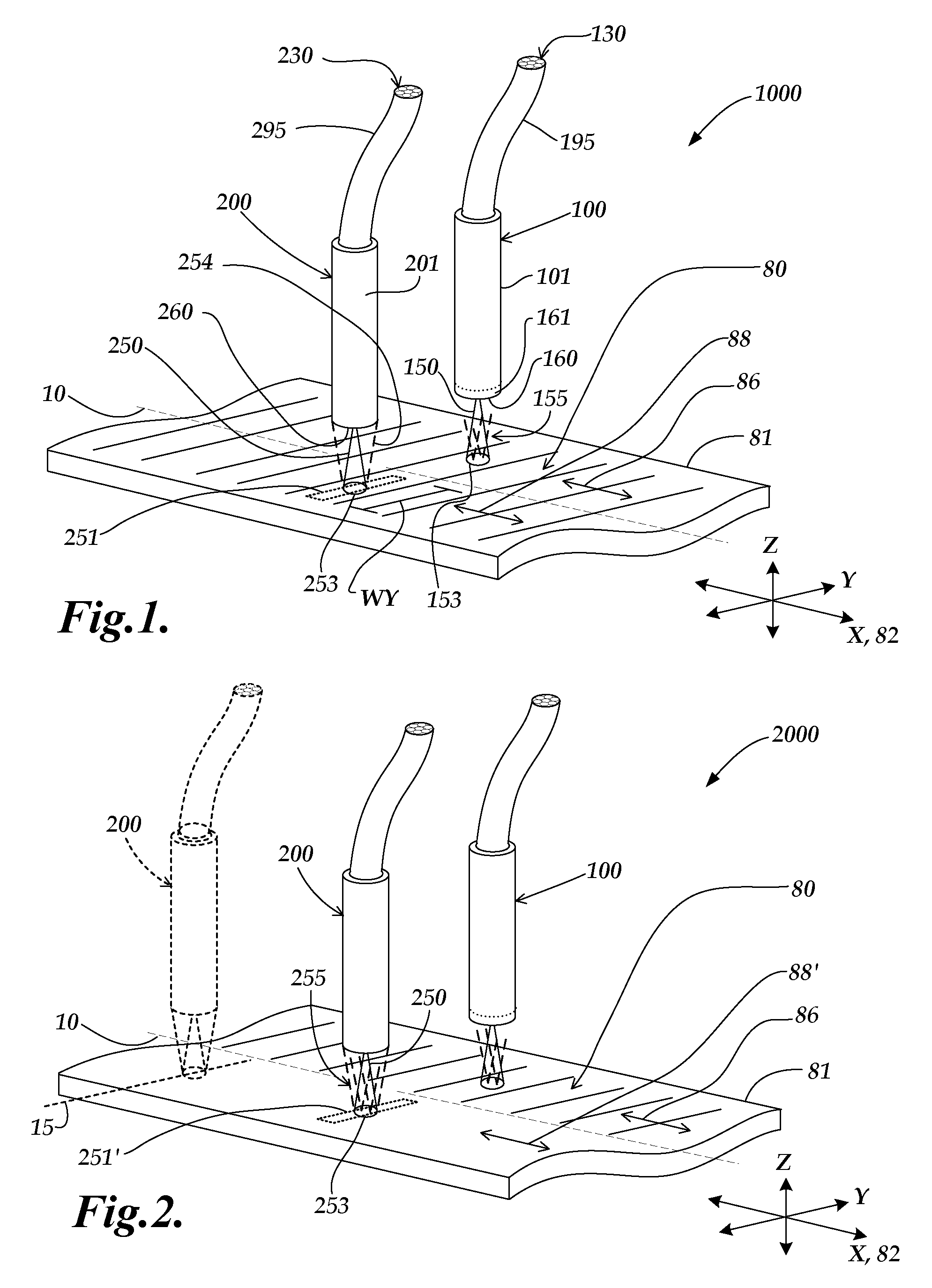
[0039]FIG. 2 is an isometric view of a miniature fiber optic readhead and scale arrangement 2000 that includes a reference signal generating configuration according to this invention. The operation of the miniature fiber optic readhead and scale arrangement 2000 is in some respects similar to that of miniature fiber optic readhead and scale arrangement 1000 of FIG. 1, and similarly numbered components may be similar or identical in form and operation, except as otherwise indicated below. As shown in FIG. 2, the miniature fiber optic readhead and scale arrangement 2000 includes a scale member 81 that includes a scale grating 80, an incremental readhead 100, and a reference mark readhead 200. A primary difference between the miniature fiber optic readhead and scale arrangement 2000 and miniature fiber optic readhead and scale arrangement 1000 is that the structure of reference scale track 88′ is different than that of reference scale track 88. In particular, at least that portion of t...
third embodiment
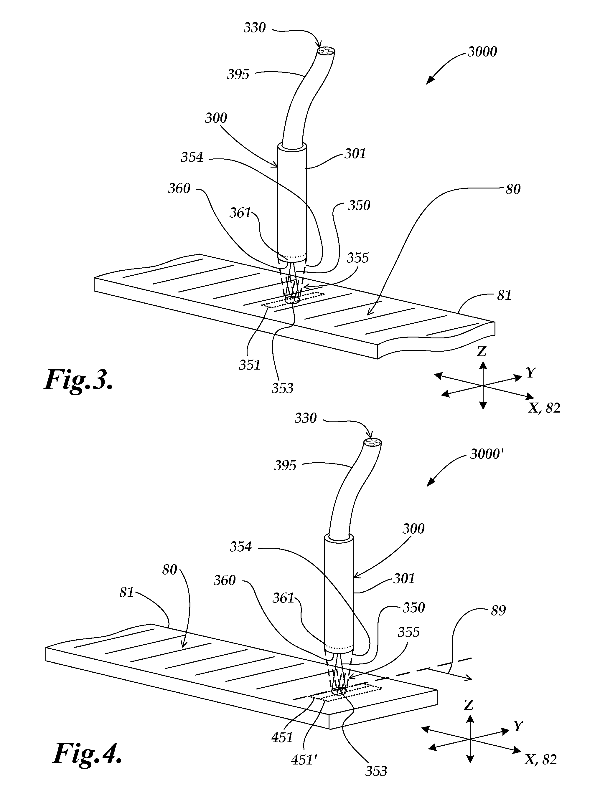
[0043]FIG. 3 is an isometric view of a miniature fiber optic readhead and scale arrangement 3000 that includes a reference signal generating configuration according to this invention. The operation of the miniature fiber optic readhead and scale arrangement 3000 is in some respects similar to that of miniature fiber optic readhead and scale arrangement 1000 of FIG. 1, and similarly numbered components may be similar or identical in form and operation, except as otherwise indicated below. As shown in FIG. 3, the miniature fiber optic readhead and scale arrangement 3000 includes a scale member 81 that has a single scale track that includes a scale grating 80 and a reference mark zone 351, and an integrated incremental and reference mark readhead 300, also referred to simply as an integrated readhead 300. The scale grating 80 may be a phase grating configured to suppress zero-order reflection. The reference mark zone 351 may include at least one mirror-like reference mark portion, as p...
PUM
 Abstract
Description
Claims
Application Information
 - R&D
- Intellectual Property
- Life Sciences
- Materials
- Tech Scout
- Unparalleled Data Quality
- Higher Quality Content
- 60% Fewer Hallucinations
Browse by: Latest US Patents, China's latest patents, Technical Efficacy Thesaurus, Application Domain, Technology Topic, Popular Technical Reports.
© 2025 PatSnap. All rights reserved.Legal|Privacy policy|Modern Slavery Act Transparency Statement|Sitemap|About US| Contact US: help@patsnap.com


