
Variable damper

a damper and variable technology, applied in the direction of shock absorbers, machine supports, transportation and packaging, etc., can solve the problems of affecting the effect of achieving favorable response and extremely difficult damping, and achieve the effect of convenient use, convenient manufacturing and maintenance, and compact design

Inactive Publication Date: 2011-06-14
HONDA MOTOR CO LTD
View PDF11 Cites 27 Cited by
  • Summary
  • Abstract
  • Description
  • Claims
  • Application Information

AI Technical Summary

Benefits of technology

The design achieves a wide range of damping forces, minimizes damping when the coil is de-energized, enhances responsiveness, and simplifies manufacturing and servicing, while maintaining performance and reducing heat generation.

Problems solved by technology

Furthermore, the damper disclosed in U.S. Pat. No. 6,260,675 requires the outer yoke to be crimped onto the end plates, and this requires special tooling in the manufacturing line and makes the servicing of the damper extremely difficult.
In the conventional dampers mentioned above, because the coil is located immediately adjacent to the inner circumferential surface of the gap or flow passage in the piston, the coil is given with a high inductance, and this was found to be detrimental to achieving a favorable response of the damper.

Method used


Image

  • Variable damper
  • Variable damper
  • Variable damper

Examples


Embodiment Construction

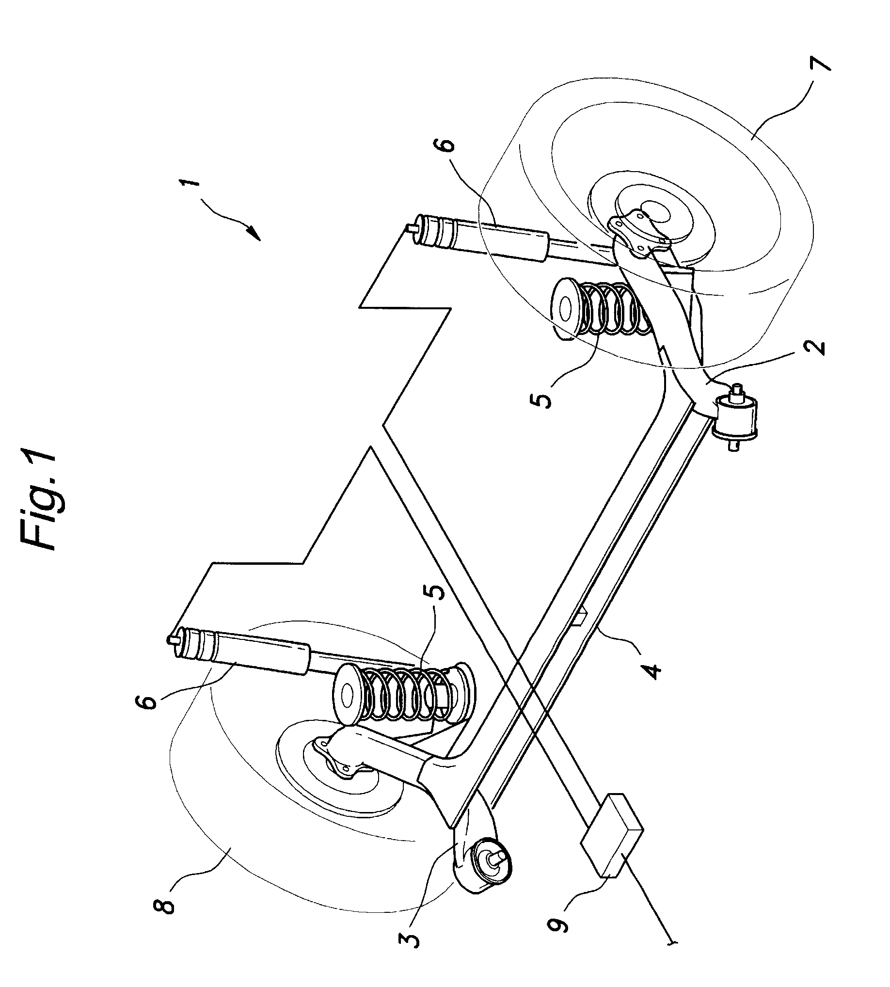
[0033]FIG. 1 shows a rear wheel suspension system 1 consisting of a H-shaped torsion beam suspension system to which the present invention is applied. This suspension system comprises a pair of trailing arms 2 and 3, a torsion beam 4 connecting intermediate parts of the trailing arms 2 and 3 with each other, a pair of coil springs 5 serving as suspension springs for the corresponding trailing arms, respectively, and a pair of dampers 6 for the corresponding trailing arms. Each damper 6 consists of a variable damping force damper using MRF (Magneto-Rheological Fluid), and is configured to vary the damping force thereof under the control of an ECU 9 mounted in a car trunk or the like.

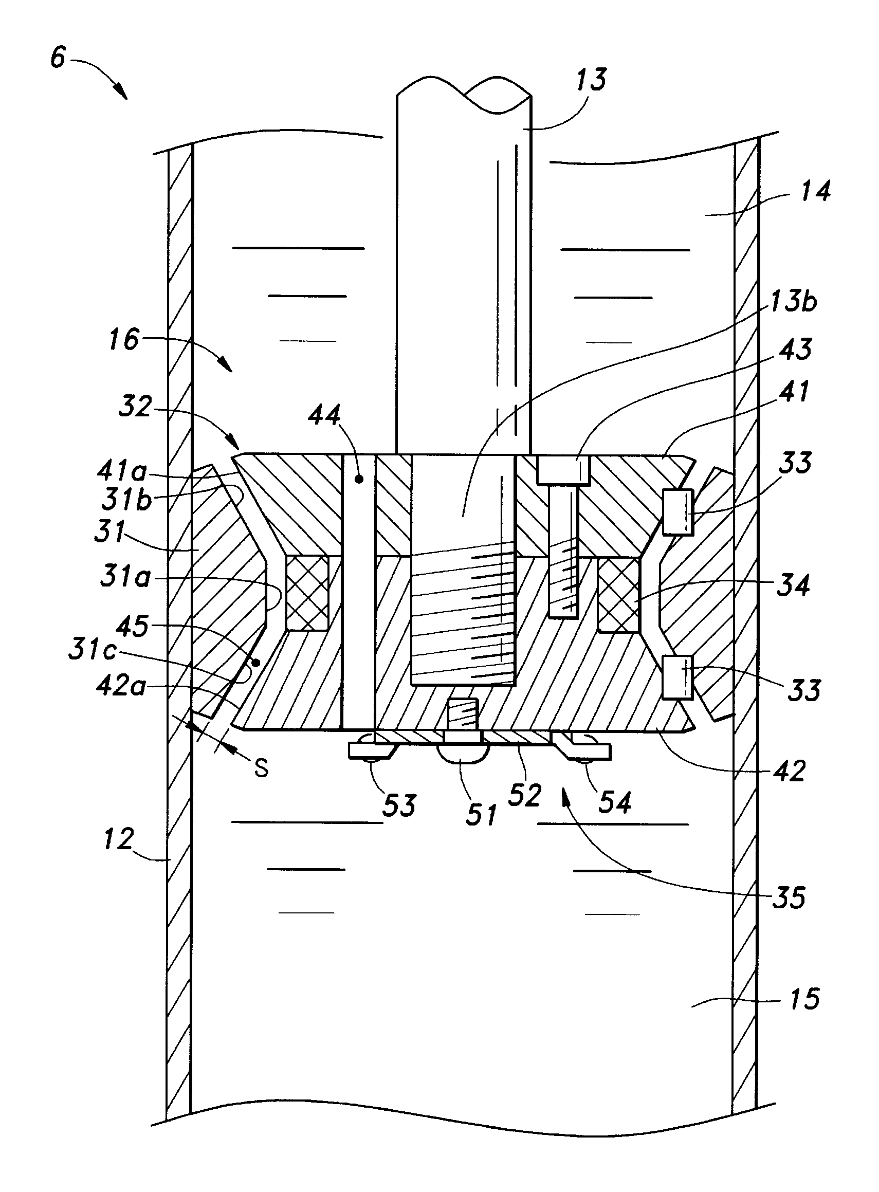
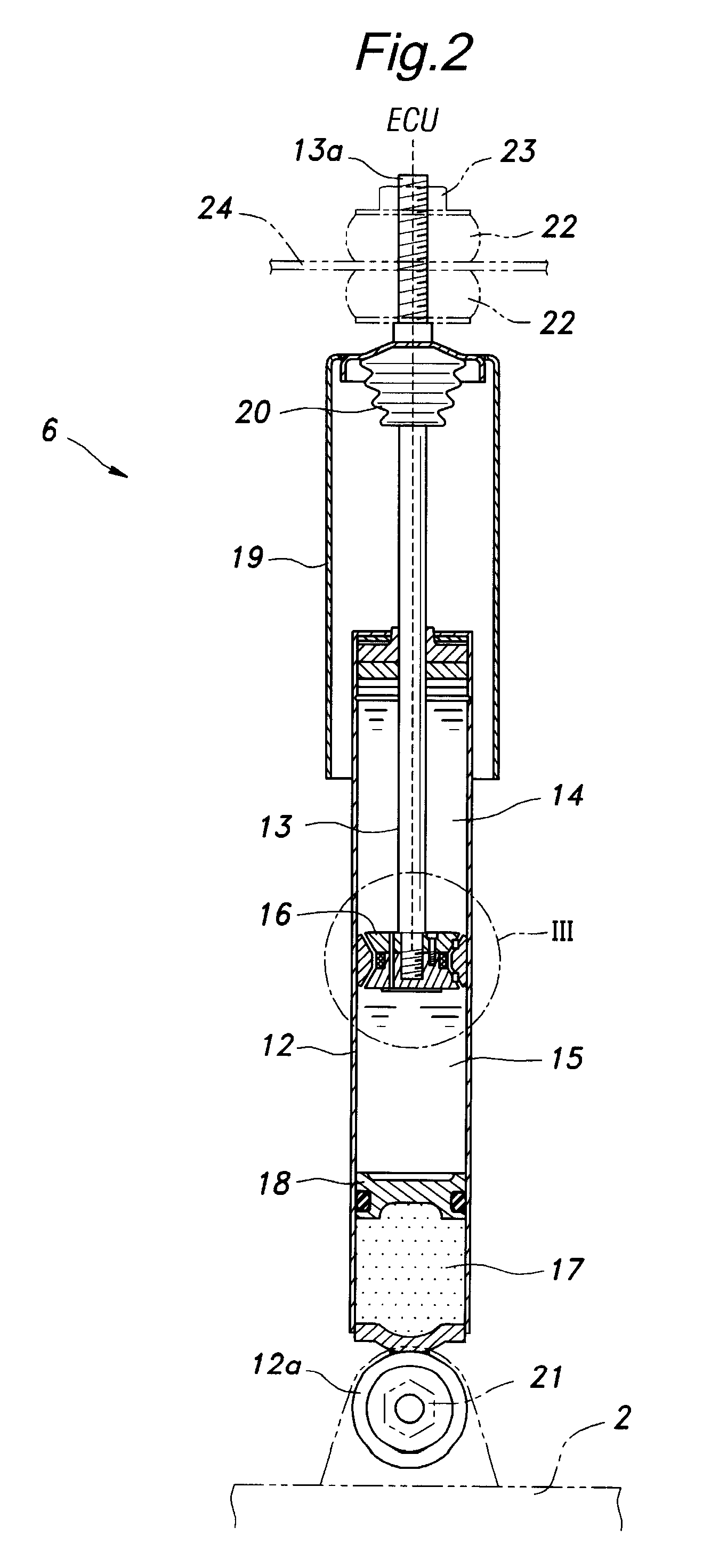
[0034]As shown in FIG. 2, the damper 6 of the illustrated embodiment consists of a mono-tube type comprising a cylindrical cylinder 12 filled with MRF, a piston rod 13 extending out of the cylinder 12 in a slidable manner, a piston 16 attached to the inner end of the piston rod 13 and separating the inter...


PUM


Abstract

In a variable damper using magneto-rheological fluid that comprises a cylinder (12) filled with the fluid, a piston (16) slidably received in the cylinder and including an inner yoke (32; 62; 126), an outer yoke (31; 64, 65; 140) and a coil (34; 130), a piston rod (13) having an inner end attached to the piston and an outer end extending out of the cylinder and a magnetic valve formed in a gap between the inner and outer yokes, at least one of the outer yoke and inner yoke consisting of at least two parts that are joined to each other in an axial direction. The two piece arrangement of the inner yoke or outer yoke allows the end plates to be omitted because the gap spacer can be installed without requiring end plates, and this contributes to a compact design and a favorable damping property. Also, the manufacturing and servicing of the damper can be simplified. When end plates (134) are used, the freedom in the positioning of the coil is increased.

Description

CROSS-REFERENCE TO RELATED APPLICATION[0001]This application claims the priority of JP Application Nos. 2007-0076707, filed Jan. 17, 2007 and 2007-281636, filed Oct. 30, 2007, the entire specifications, claims and drawings of which are incorporated herewith by reference.TECHNICAL FIELD[0002]The present invention relates to a variable shock absorber or damper that can produce a variable damping force for use in an automotive wheel suspension system, and in particular to a variable damper that is highly compact and can vary the damping force over a wide range.BACKGROUND OF THE INVENTION[0003]Various forms of variable dampers have been proposed for use in wheel suspension systems for the purposes of improving the ride quality and achieving a motion stability of the vehicle. In a common conventional variable damper, a rotary valve is incorporated in the piston for varying an effective area of an orifice that communicates the two chambers on either side of the piston with each other, and...

Claims


Application Information

Patent Timeline
Patent Type & Authority Patents(United States)
IPC IPC(8): F16F9/53F16F9/30
CPCB60G17/06F16F9/535B60G21/051B60G2202/24
Inventor SEKIYA, SHIGENOBUAZEKATSU, YOSHITOMO
Owner HONDA MOTOR CO LTD
Learn More