
Method of joining composite honeycomb sections

a composite sandwich panel and honeycomb technology, applied in the field of composite structures, can solve the problems of aircraft engine noise and aircraft engine noise, and achieve the effect of reducing the noise of aircraft engines

Inactive Publication Date: 2011-06-07
ROHR INC
View PDF17 Cites 14 Cited by
  • Summary
  • Abstract
  • Description
  • Claims
  • Application Information

AI Technical Summary

Benefits of technology

The invention is a method for joining edges of adjacent honeycomb core panel sections. The method involves forming edges on each section with a plurality of cell walls, and then mechanically interlocking the cell walls of the edges to create a joint. This allows for a stronger and more secure connection between the sections. The invention also includes a tool for facilitating the interlocking process. The technical effect of this invention is a more reliable and durable connection between honeycomb core panels.

Problems solved by technology

Aircraft engines generate a substantial amount of noise.
In high population areas and other noise controlled environments, aircraft engine noise can be problematic.

Method used


Image

  • Method of joining composite honeycomb sections
  • Method of joining composite honeycomb sections
  • Method of joining composite honeycomb sections

Examples


Embodiment Construction

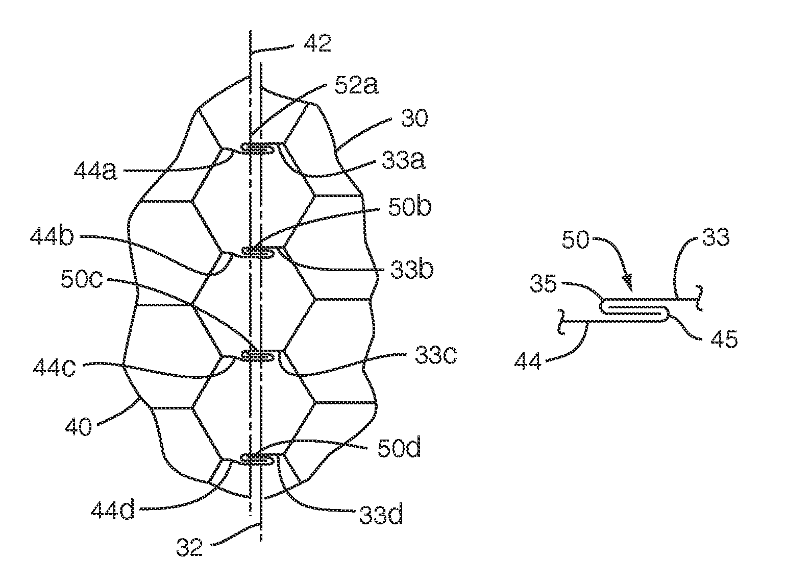
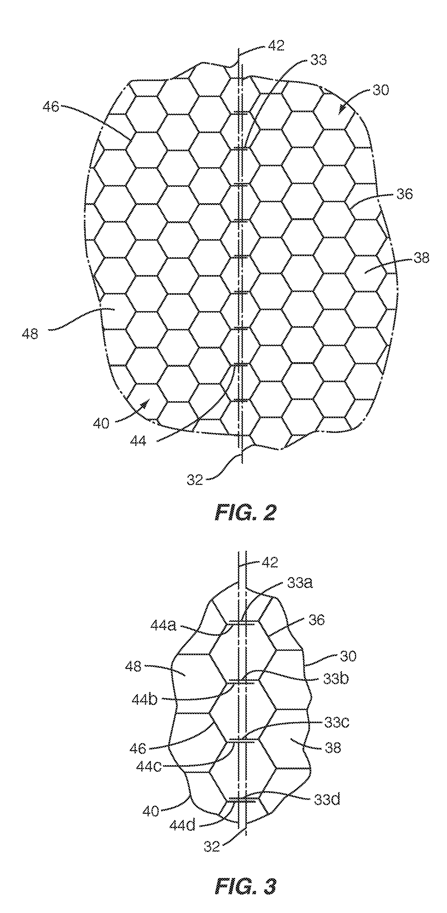
[0025]One method of joining honeycomb panel sections according to the invention is shown in FIGS. 2-4. As shown in FIGS. 2 and 3, a first honeycomb sheet 30 includes an array of open cells 38 formed by a matrix of thin cell walls 36. The first honeycomb sheet 30 further includes a first edge 32 having a first plurality of edge cell walls 33 along the first edge 32. A second honeycomb sheet 40 includes a second array of cells 48 formed by a matrix of thin cell walls 46. The second honeycomb sheet 40 includes a second edge 42 having a second plurality of edge cell walls 44 along the second edge 42. Preferably, the cell walls 33, 36, 44, 46 are constructed of a ductile metal foil such as aluminum or titanium. Alternatively, the cell walls 33, 36, 44, 46 may be constructed of one or more other ductile materials.

[0026]As shown in FIGS. 2 and 3, the first edge 32 and the second edge 42 are positioned proximate to each other such that at least a portion of the first plurality of edge cell ...


PUM

PropertyMeasurementUnit
sizeaaaaaaaaaa
permeableaaaaaaaaaa
sound energyaaaaaaaaaa

Abstract

The invention includes a method of joining edges of adjacent honeycomb core panel sections. In one embodiment, the method includes forming a first edge along a first cellular core panel section. The first edge includes a first plurality of edge cell walls along the first edge. The method further includes forming a second edge along a second cellular core panel section, wherein the second edge includes a second plurality of edge cell walls along the second edge. The first edge is positioned proximate to the second edge. At least a portion of at least one of the first plurality of edge cell walls is mechanically interlocked with at least a portion of at least one of the second plurality of edge cell walls to form a joint therebetween. The invention also includes a composite structure at least partially produced by such a method.

Description

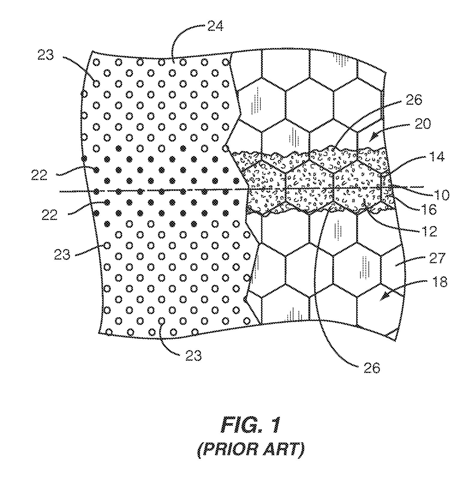
FIELD OF THE INVENTION[0001]The invention generally relates to composite structures, and more particularly relates to methods of joining honeycomb composite sandwich panel sections in edge-to-edge relation and composite panels resulting from such methods.BACKGROUND[0002]Aircraft engines generate a substantial amount of noise. In high population areas and other noise controlled environments, aircraft engine noise can be problematic. In order to reduce the noise generated by modern aircraft engines, aircraft manufacturers often line the aircraft engine nacelle and surrounding engine areas with acoustic liners that at least partially suppress the amount of noise radiated by the engines to the surrounding environment. Such acoustic liners typically include honeycomb composite sandwich panels configured to absorb or dissipate sound energy. As used herein, the term “honeycomb” refers to an array of open cells formed by a matrix of interconnected cell walls. Though such cells often have he...

Claims


Application Information

Patent Timeline
Patent Type & Authority Patents(United States)
IPC IPC(8): B23P11/00
CPCB32B3/12G10K11/172B32B3/18B64D2033/0206Y10T29/49718Y10T428/24149Y10T29/4957B32B2605/18Y10T29/49908Y10T29/4973Y10T29/49936Y10T428/12493B32B2307/102Y10T29/49924B21D39/021B23B3/12F16B5/01
Inventor DOUGLAS, ALAN RICHARD
Owner ROHR INC
Learn More