
Method and device for increasing an optical system focal depth

a technology of optical system and focal depth, which is applied in the field of optical system focal depth increase, can solve the problems of deterioration of distance vision or far vision, and comes “at the expense” of distance vision, and achieve the effect of increasing the focal depth of an optical system

Active Publication Date: 2011-05-31
CARL ZEISS MEDITEC AG
View PDF9 Cites 12 Cited by
  • Summary
  • Abstract
  • Description
  • Claims
  • Application Information

AI Technical Summary

Benefits of technology

It is an object of the present invention to propose a method and an appertaining device with which an increase in the focal depth of an optical system can be achieved that leads to an improvement in the near vision without an associated deterioration of the distance vision. An increase in the focal depth is to be achieved that is refraction-neutral for the distance vision.
Thus, if the coefficients are selected in such a way that “only” the encircled energy criterion is fulfilled, then after the ablation has been performed, no exact point focusing is achieved along the range of depth. However, this is not a drawback as long as the unsharpness is not greater than the diameter of a photoreceptor cell. In fact, a focusing that is more exact than the diameter of a photoreceptor cell cannot be detected by the photoreceptor cells of the retina anyway. By turning to the encircled energy criterion, the profile can thus be simplified or selected “more coarsely”, without this reducing the quality of the correction that has been made.

Problems solved by technology

This results in a deterioration of the distance vision or far vision.
Consequently, with the known method, creating a fourth-order aberration achieves an improvement of the near vision in cases of presbyopia, but this comes “at the expense of” the distance vision.

Method used


Image

  • Method and device for increasing an optical system focal depth
  • Method and device for increasing an optical system focal depth
  • Method and device for increasing an optical system focal depth

Examples


Embodiment Construction

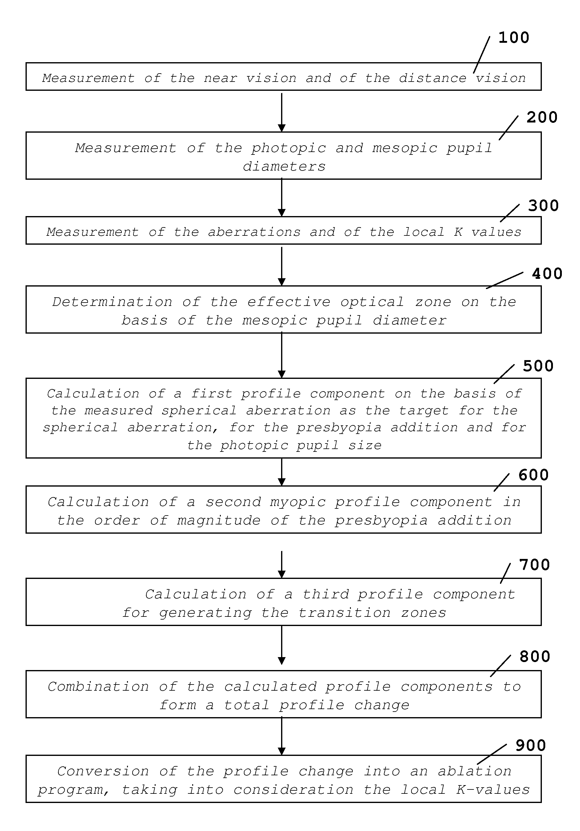
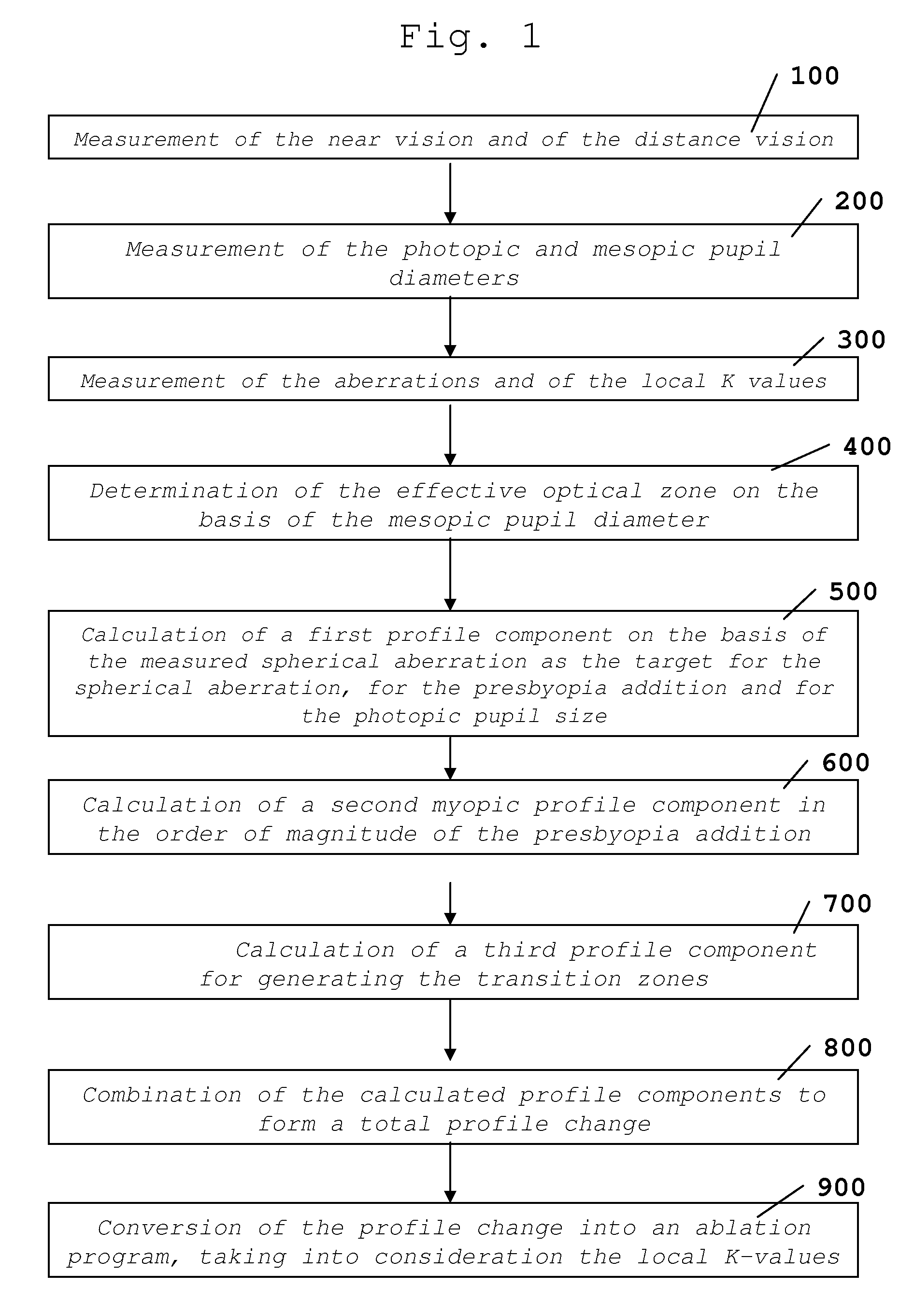
The method according to the invention will now be explained with reference to FIG. 1.

A method for multifocal corneal surgery for the correction of presbyopia is described. This method for the correction of presbyopia can be performed in emmetropic eyes, i.e. in eyes that are exclusively presbyopic but that otherwise have normal vision, and also in shortsighted (myopic), farsighted (hyperopic) and / or astigmatic eyes that are additionally presbyopic.

At this juncture, it should be pointed out that the flow diagram according to FIG. 1 exclusively shows the method for emmetropic eyes. There are further method steps in the case of eyes with additional visual inadequacies.

As can be seen in FIG. 1, the method starts in that the near vision and the distance vision in the eye that is to be treated are measured (Step 100). Then the pupil size, i.e. the diameter of the pupil in daylight (photopic) as well as under dusk conditions (mesopic) is determined (Step 200). Then, if applicable, the valu...


PUM


Abstract

A method and device for modifying optical system properties by means of a continuously multifocal profile, wherein said profile comprises a component for increasing the optical system focal depth and is calculated according to a fourth-order Zernike polynom. The aim of said invention is to avoid the eye base refraction and, for this purpose, said focal depth increasing component is also calculated according to the second-order Zernike polynom.

Description

This is a U.S. National Phase application under 35 U.S.C. §371 of International Application No. PCT / EP2006 / 002692, filed Mar. 23, 2006 and claims the benefit of German Patent Application No. 10 2005 013 558.7, filed on Mar. 23, 2005. The International Application was published in German on Sep. 28, 2006 as WO 2006 / 100086 under PCT Article 21 (2).The invention relates to a method for changing the properties of an optical system by means of a continuously multifocal profile, whereby the profile comprises a component for increasing the focal depth of the optical system and the component for increasing the focal depth is calculated at least on the basis of a fourth-order Zernike polynomial.BACKGROUNDInternational patent application WO 2004 / 052253 A1 describes an excimer laser unit and a corresponding control method for performing a corneal ablation to reduce presbyopia. Here, the excimer laser unit is controlled in such a way that, through the ablation of the cornea, a slightly positive...

Claims


Application Information

Patent Timeline
Patent Type & Authority Patents(United States)
IPC IPC(8): A61B19/00
CPCA61F9/00808A61F9/00838A61F2009/00848A61F2009/00872A61F2009/0088A61F2009/00882A61F2009/00895
Inventor SCHROEDER, ECKHARDWOTTKE, MATTHIASVON BUENAU, RUDOLF
Owner CARL ZEISS MEDITEC AG
Learn More