
Methods and apparatus for differential phase-contrast fan beam CT, cone-beam CT and hybrid cone-beam CT

a technology of phase-contrast fan beam and differential phase-contrast fan beam, which is applied in the field of phase-contrast cone beam computed tomography (ct) imaging, can solve problems such as limiting its performance, and achieve the effect of increasing spatial resolution

Active Publication Date: 2011-05-24
UNIVERSITY OF ROCHESTER
View PDF23 Cites 79 Cited by
  • Summary
  • Abstract
  • Description
  • Claims
  • Application Information

AI Technical Summary

Benefits of technology

[0016]It is therefore an object of the invention to allow an increase in spatial resolution without increasing the dose to a prohibited level.
[0017]It is therefore other object of the invention to allow substantially reduce x-ray radiation dose to a patient without reducing spatial resolution and contrast to noise ratio.

Problems solved by technology

However, when imaging soft tissues including breast tissues, the low absorption contrast differences of the breast structures (benign and malignant) limit its performance.

Method used


Image

  • Methods and apparatus for differential phase-contrast fan beam CT, cone-beam CT and hybrid cone-beam CT
  • Methods and apparatus for differential phase-contrast fan beam CT, cone-beam CT and hybrid cone-beam CT
  • Methods and apparatus for differential phase-contrast fan beam CT, cone-beam CT and hybrid cone-beam CT

Examples


Embodiment Construction

[0033]Preferred embodiments of the present invention will be set forth in detail with reference to the drawings, in which like reference numerals refer to like elements or steps throughout.

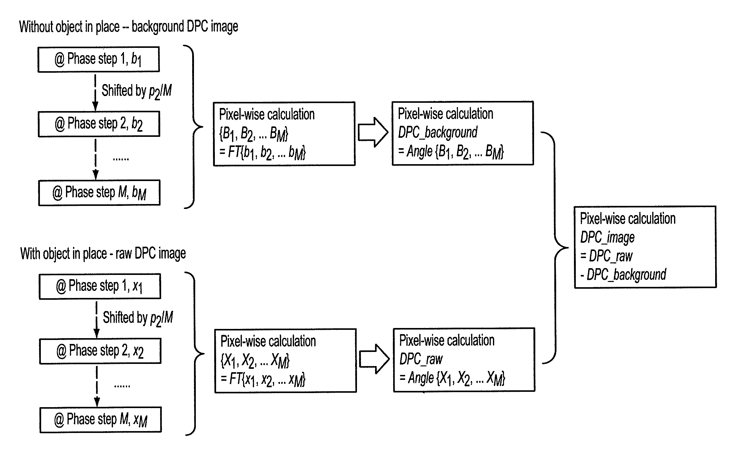
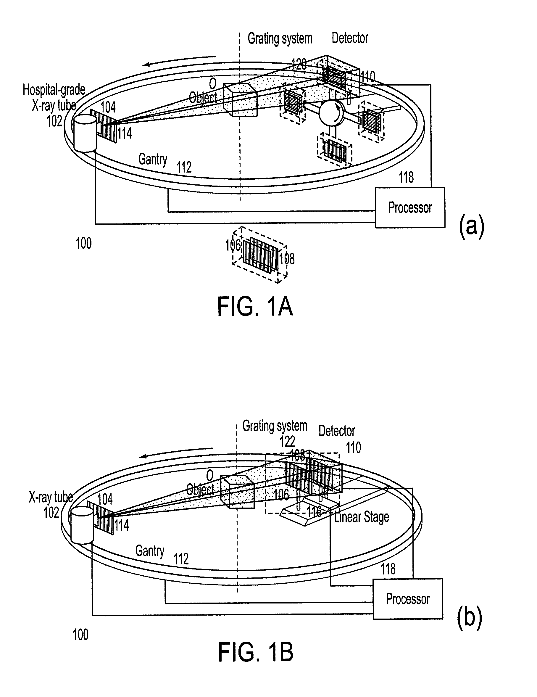
[0034]A first preferred embodiment is directed to a differential phase-contrast cone-beam CT system (DPC-CBCT) for in vivo clinical imaging using the differential phase-contrast imaging technique. As shown in FIGS. 1A and 1B, such a DPC-CBCT system 100 includes a hospital-grade x-ray tube 102 with a source grating 104, a high-resolution detector 110 and a grating system mounted on a gantry 112. To ensure the mechanical precision and stability, the grating system can be designed either as the grating system 120 in FIG. 1A or as the grating system 122 in FIG. 1B. The purpose of grating system is to produce different phase steps that are defined as relative displacements between the phase grating 106 and the analyzer grating 108 in the direction perpendicular to grating lines. Grating system 120 is c...


PUM

PropertyMeasurementUnit
cone angleaaaaaaaaaa
diameteraaaaaaaaaa
sizeaaaaaaaaaa

Abstract

A device for imaging an object, such as for breast imaging, includes a gantry frame having mounted thereon an x-ray source, a source grating, a holder or other place for the object to be imaged, a phase grating, an analyzer grating, and an x-ray detector. The device images objects by differential-phase-contrast cone-beam computed tomography. A hybrid system includes sources and detectors for both conventional and differential-phase-contrast computed tomography.

Description

REFERENCE TO RELATED APPLICATION[0001]The present application claims the benefit of U.S. Provisional Patent Application No. 61 / 156,642, filed Mar. 2, 2009, whose disclosure is hereby incorporated by reference in its entirety into the present disclosure.STATEMENT OF GOVERNMENT INTEREST[0002]This invention was made with government support under Grant Nos. R01 9 HL078181 and 4 R33 CA94300 awarded by National Institutes of Health. The government has certain rights in the invention.FIELD OF THE INVENTION[0003]The present invention is directed to cone-beam computed tomography (CT) imaging and more particularly to phase-contrast cone-beam CT for such uses as breast imaging.DESCRIPTION OF RELATED ART[0004]According to the National Cancer Institute, one out of eight women will be diagnosed with breast cancer in their lifetime. And while a reduction in mortality from breast cancer is evident in published reports, each year 40,000 women will die of the disease.[0005]The optimal breast imaging ...

Claims


Application Information

Patent Timeline
Patent Type & Authority Patents(United States)
IPC IPC(8): G01N23/04
CPCA61B6/032A61B6/484A61B6/502A61B6/027A61B6/4291G21K2207/005A61B6/4035A61B6/4085A61B6/4417A61B6/4435A61B6/5205A61B6/4014
Inventor NING, RUOLACAI, WEIXING
Owner UNIVERSITY OF ROCHESTER
Learn More