
Electronic device enclosure

a technology for electronic devices and enclosures, applied in the field of enclosures, can solve the problems of inconvenient assembly or disassembly, difficult to disassemble the cover from the housing, and need strong external for

Inactive Publication Date: 2011-05-24
HONG FU JIN PRECISION IND (SHENZHEN) CO LTD +1
View PDF2 Cites 15 Cited by
  • Summary
  • Abstract
  • Description
  • Claims
  • Application Information

AI Technical Summary

Benefits of technology

[0006]Another typical electronic device enclosure includes a housing, a cover, a plurality of latching hooks formed on the cover, and a plurality of latching steps defined on the housing corresponding to the latching hooks. The cover is fixed on the housing by applying an external force to press the cover until the latching hooks are latched with the latching steps. However, a strong external force is necessary to detach the latching hooks from the latching steps to remove the cover from the housing. Therefore, it is difficult to disassemble the cover from the housing. Moreover, the latching hooks may break during disassembly from the strong external force, thereby damaging the electronic device enclosure.

Problems solved by technology

However, it is very inconvenient for assembly or disassembly, because screws or bolts must be screwed or unscrewed one by one.
In addition, the electronic device enclosure can deform after multiple assemblies or disassemblies, thereby causing an unsatisfactory.
However, a strong external force is necessary to detach the latching hooks from the latching steps to remove the cover from the housing.
Therefore, it is difficult to disassemble the cover from the housing.
Moreover, the latching hooks may break during disassembly from the strong external force, thereby damaging the electronic device enclosure.

Method used


Image

  • Electronic device enclosure
  • Electronic device enclosure
  • Electronic device enclosure

Examples


Embodiment Construction

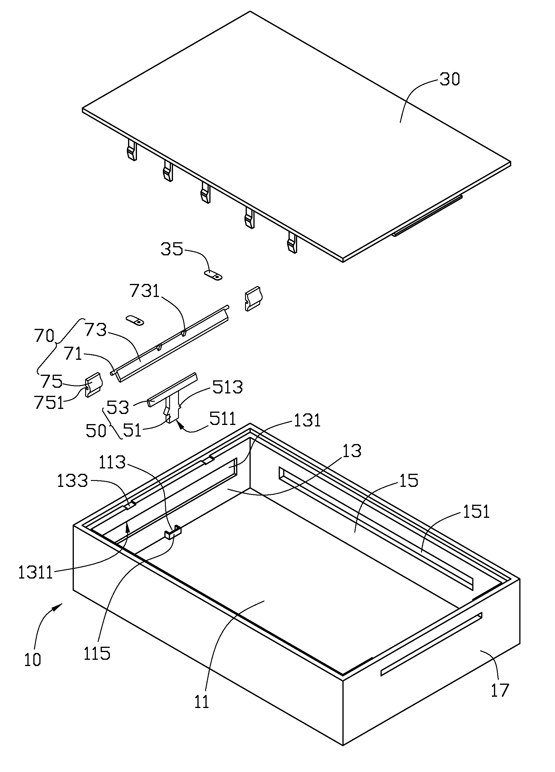
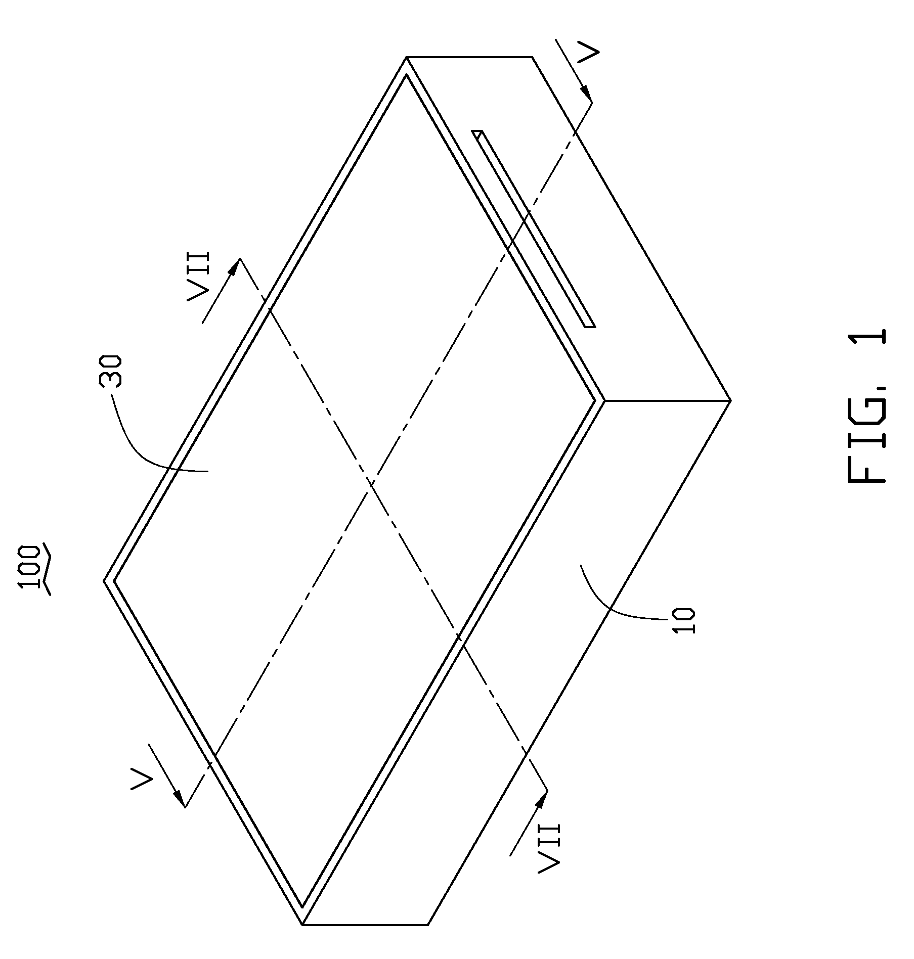
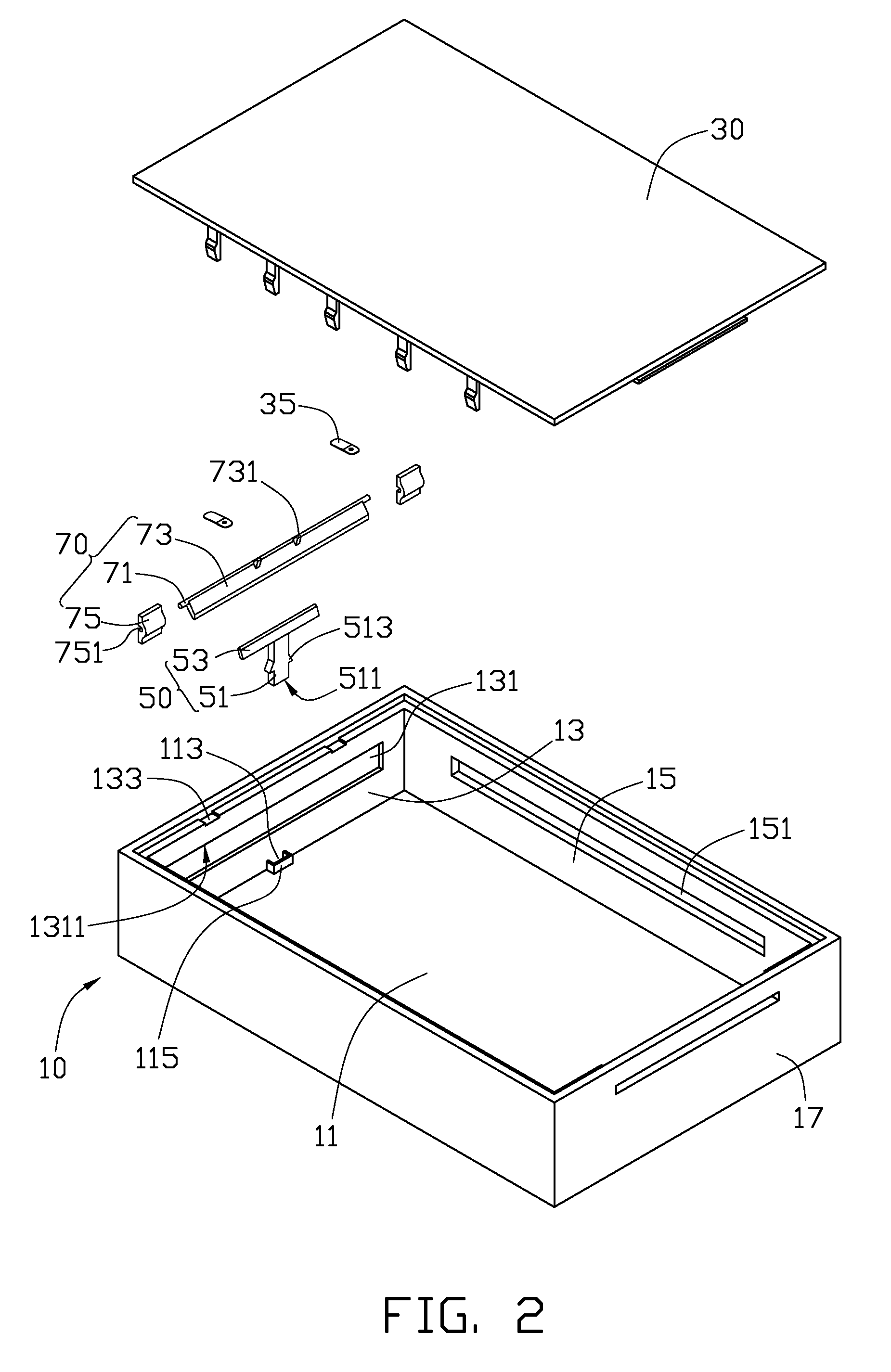
[0017]Referring to FIGS. 1 and 2, an electronic device enclosure 100 includes a housing 10, a cover 30 fixed on the housing 10, an operating member 50 positioned in the housing 10, and an urging assembly 70 assembled in the housing 10.

[0018]The housing 10 includes a rectangular base 11, a first sidewall 13, two second sidewalls 15, and a third sidewall 17. Each sidewall extends substantially perpendicularly from a periphery of the base 11, with the first sidewall 13 opposite the third sidewall 17, and the two second sidewalls 15 opposite to each other.

[0019]A mounting portion 115 extends from an end of the base 11 adjacent to the first sidewall 13. The mounting portion 115 and the first sidewall 13 cooperatively define a mounting hole 113 to engage with the operating member 50. The mounting hole 113 runs through the base 11. The first sidewall 13 defines a first latching portion 131 in an inner surface of the first sidewall 13, and two limiting grooves 133 in a top surface of the fi...


PUM


Abstract

An electronic device enclosure includes a housing and a cover fixed on the housing. The housing defines a first latching portion, and the cover defines a plurality of first latching hooks to engage with the first latching portion. The electronic device enclosure further includes an urging assembly rotatably assembled in the housing to contact the first latching hooks, and an operating member positioned in the housing and contacting the urging assembly. The operating member is capable of pushing the urging assembly to rotate so that the first latching hooks bends and disengages from the first latching portion.

Description

BACKGROUND[0001]1. Technical Field[0002]The present disclosure relates to an enclosure for use in an electronic device.[0003]2. Description of Related Art[0004]Electronic devices, such as desktop computers, notebook computers, and digital video disc players, are very popular and widely used. An electronic device generally includes an enclosure securing electronic components therein.[0005]A typical electronic device enclosure includes a housing and a cover fixed on the housing to cover an opening of the housing. The cover may be fixed on the housing by screws or bolts. However, it is very inconvenient for assembly or disassembly, because screws or bolts must be screwed or unscrewed one by one. In addition, the electronic device enclosure can deform after multiple assemblies or disassemblies, thereby causing an unsatisfactory.[0006]Another typical electronic device enclosure includes a housing, a cover, a plurality of latching hooks formed on the cover, and a plurality of latching ste...

Claims


Application Information

Patent Timeline
Patent Type & Authority Patents(United States)
IPC IPC(8): H05K5/00
CPCH05K5/0013Y10S248/906
Inventor TANG, ZI-MING
Owner HONG FU JIN PRECISION IND (SHENZHEN) CO LTD
Learn More