
Lens holder and lens apparatus having same

a technology of lens holder and lens holder, which is applied in the field of lenses, can solve the problems of difficult reuse of lens holder or piezoelectric actuator, and the disassembly of piezoelectric actuator and the lens holder

Inactive Publication Date: 2010-06-01
HON HAI PRECISION IND CO LTD
View PDF1 Cites 2 Cited by
  • Summary
  • Abstract
  • Description
  • Claims
  • Application Information

AI Technical Summary

Benefits of technology

[0004]Generally, a piezoelectric actuator includes a vibrator and a driving rod coupled thereto. In a lens apparatus, a lens holder integrally formed with a transmission portion is employed and coupled to a piezoelectric actuator by insertion of the driving rod through the transmission portion. The piezoelectric actuator and the lens holder are difficult to disassemble. As a result, in the event of damage, it is difficult to reuse the lens holder or the piezoelectric actuator, if either of them is still workable.

Problems solved by technology

The piezoelectric actuator and the lens holder are difficult to disassemble.
As a result, in the event of damage, it is difficult to reuse the lens holder or the piezoelectric actuator, if either of them is still workable.

Method used


Image

  • Lens holder and lens apparatus having same
  • Lens holder and lens apparatus having same
  • Lens holder and lens apparatus having same

Examples


Embodiment Construction

[0012]Embodiments of the present lens holder and lens apparatus will now be described in detail with references to the drawings.

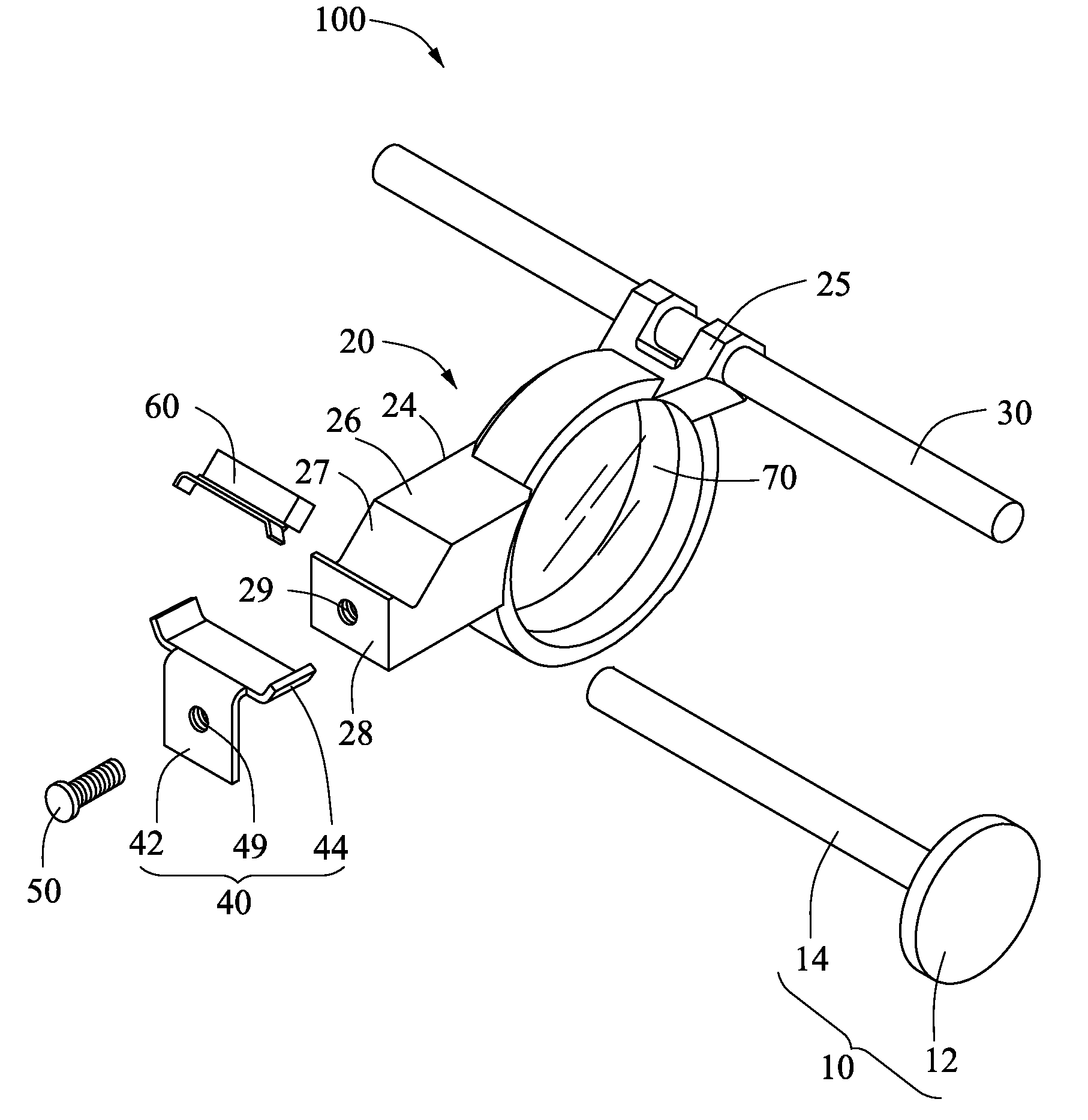
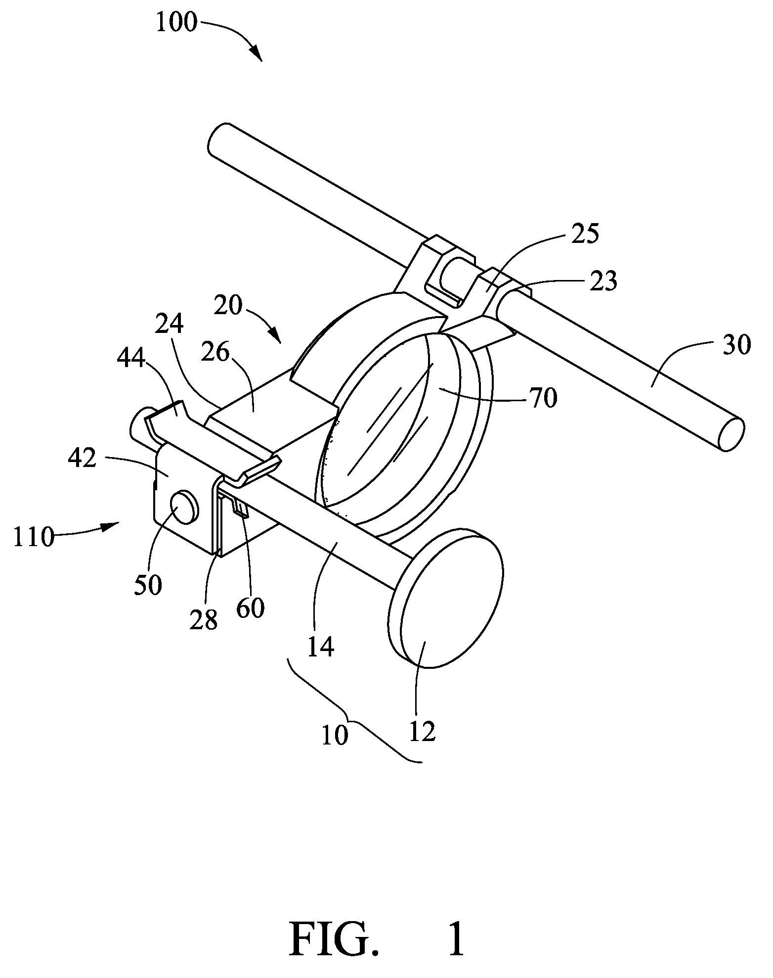
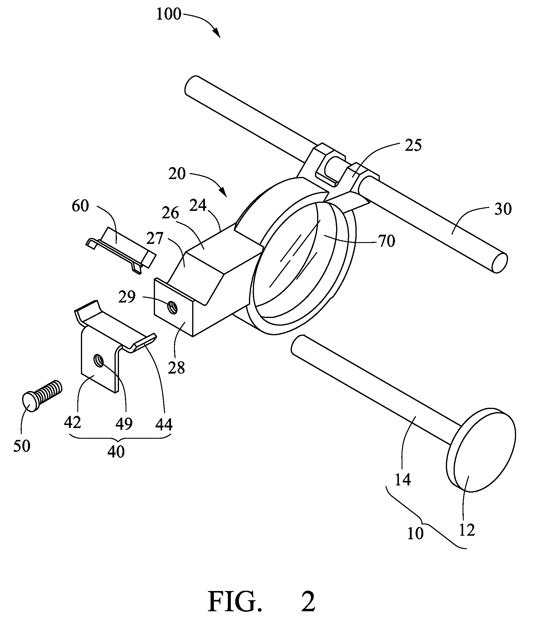
[0013]Referring to FIG. 1 and FIG. 2, a lens apparatus 100, according to a first exemplary embodiment, is shown. The lens apparatus 100 includes a lens 70, an actuator 10, a guide rod 30, and a lens holder 110.

[0014]The lens holder 110 includes a lens carrier 20, a transmission member 24, a guiding member 25, and a fixing member 40. The lens carrier 20 is barrel-shaped. The lens 70 is received in the lens carrier 20. The transmission member 24 and the guiding member 25 are fixed to the lens carrier 20. In this embodiment, the lens carrier 20, the transmission member 24, and the guiding member 25 are integrally formed.

[0015]The transmission member 24 has a first peripheral surface 26 adjacent to the lens carrier 20 and a second peripheral surface 28 perpendicular to the first peripheral surface 26. The first peripheral surface 26 defines a groove 27 therein....


PUM


Abstract

A lens holder coupling a lens to an actuator is disclosed. The actuator includes a vibrator and a driving rod coupled to the vibrator along a vibration direction of the vibrator. The lens holder includes a lens carrier, a transmission member, a guiding member, and a fixing member. The lens carrier is configured for accommodating the lens. The transmission member connected to the lens carrier defines a groove having a transmission axis parallel to an optical axis of the lens receiving the driving rod. The guiding member connected to the lens carrier defines a hole receiving a guide rod substantially parallel to the optical axis of the lens. The fixing member includes a main body and an elastic sheet, the main body being fixed to the transmission member, the elastic sheet extending from the main body and covering the groove and configured for elastically contacting the driving rod.

Description

BACKGROUND[0001]1. Technical Field[0002]The invention relates to lenses and, more particularly, to a lens holder coupling a lens to an actuator and lens apparatus having the same.[0003]2. Description of the Related Art[0004]Generally, a piezoelectric actuator includes a vibrator and a driving rod coupled thereto. In a lens apparatus, a lens holder integrally formed with a transmission portion is employed and coupled to a piezoelectric actuator by insertion of the driving rod through the transmission portion. The piezoelectric actuator and the lens holder are difficult to disassemble. As a result, in the event of damage, it is difficult to reuse the lens holder or the piezoelectric actuator, if either of them is still workable.[0005]Therefore, it is desirable to provide a lens holder and lens apparatus addressing the described limitations.SUMMARY[0006]A lens holder coupling a lens to an actuator is disclosed. The actuator includes a vibrator and a driving rod coupled to the vibrator ...

Claims


Application Information

Patent Timeline
Patent Type & Authority Patents(United States)
IPC IPC(8): G02B7/02
CPCG02B7/08
Inventor KUO, PEI-CHINGLIN, HSIN-LIWU, YUNG-TENGWANG, SHENG-AN
Owner HON HAI PRECISION IND CO LTD
Learn More