
Wideband RF amplifiers

a wideband rf amplifier and amplifier technology, applied in the direction of dc-amplifiers with dc-coupled stages, differential amplifiers, amplifiers with semiconductor devices/discharge tubes, etc., can solve the problems of slow operation speed, increased power consumption, and inability to produce voltage waveforms, so as to reduce the amount of operational dc current, reduce dc power consumption, and fast risetime

Active Publication Date: 2011-05-17
ANALOG DEVICES INC
View PDF4 Cites 14 Cited by
  • Summary
  • Abstract
  • Description
  • Claims
  • Application Information

AI Technical Summary

Benefits of technology

This approach enables amplification of signals over a wide range of frequencies with fast risetimes and reduced DC power consumption, effectively driving components like mixers and modulators in RF communication systems while utilizing lower voltage devices and minimizing power usage.

Problems solved by technology

However, such components typically suffer from high parasitic capacitance and thus are not able to produce voltage waveforms with large swings and sharp risetimes over a wide range of frequencies.
Moreover, such components tend to have larger geometries which result in slower operation speed, and typically utilize large DC currents resulting in higher power consumption.
Such techniques, however, still do not enable the LO amplifier to operate over a wide range of frequencies with reasonable DC power consumption.

Method used


Image

  • Wideband RF amplifiers
  • Wideband RF amplifiers
  • Wideband RF amplifiers

Examples


Embodiment Construction

[0023]In general, the present invention pertains in various embodiments to devices and methods for amplifying an input signal. To provide an overall understanding of the invention, certain illustrative embodiments are described, including devices and methods for amplifying an input signal in, e.g. radio frequency (RF) range from about 10 MHz to about 5000 MHz, in a RF communication system by using stacked amplifying modules.

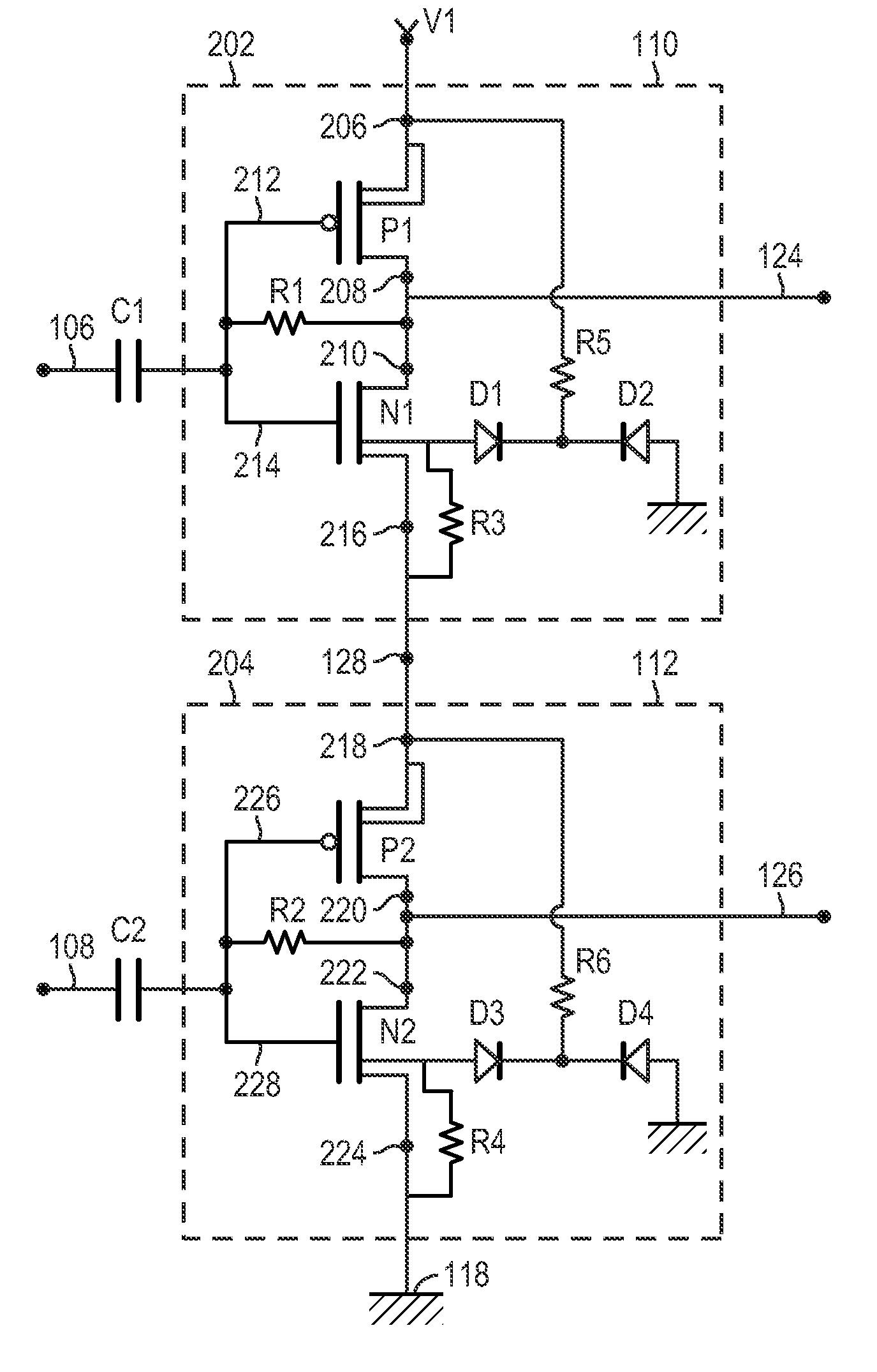
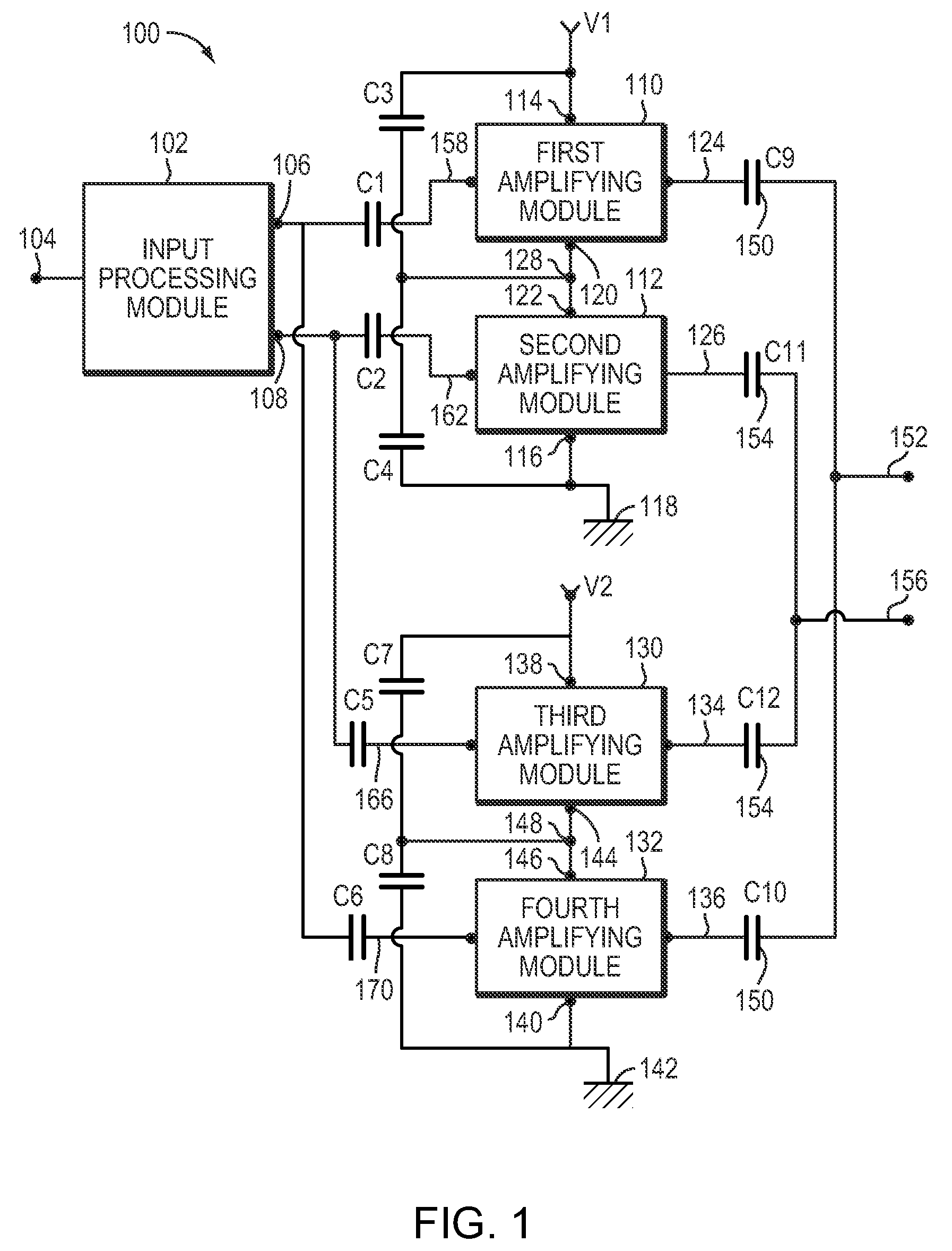
[0024]Refer to FIG. 1, which depicts an electronic device 100 for amplifying an input signal according to an illustrative embodiment of the invention. The illustrated device includes an input processing module 102 which may be configured to receive an input signal 104 and process it to generate a first signal 106 and a second signal 108. In one embodiment, the input processing module 102 includes a differential amplifier. The differential amplifier may have two input terminals, with one terminal being connected to an electrical ground and the other terminal recei...


PUM


Abstract

A device for amplifying signals over a wide frequency range features stacked amplifying modules connected between a DC voltage source and an electrical ground. The stacking configuration reuses the DC current produced the voltage source, and thus reduces the amount of operational DC current permitting the use of lower voltage, higher frequency devices to be used. The amplifying modules are fed signals which are different versions of an input signal, and the output signals are AC coupled using capacitors to balance out gain imbalances and asymmetries between the amplifying modules.

Description

FIELD OF THE INVENTION[0001]The present invention relates generally to wideband amplifiers used in RF communication systems, and more specifically, to current-stacked amplifiers.BACKGROUND OF THE INVENTION[0002]Modem communication systems require components, such as a local oscillator (LO) amplifier, which operate in the radio frequency (RF) spectrum and drive other components, e.g., mixers, modulators, and demodulators. However, such components typically suffer from high parasitic capacitance and thus are not able to produce voltage waveforms with large swings and sharp risetimes over a wide range of frequencies. Moreover, such components tend to have larger geometries which result in slower operation speed, and typically utilize large DC currents resulting in higher power consumption.[0003]Current approaches to overcome this problem include using reactive matching techniques, such as using a resonant LC tank circuit at the output of a LO amplifier to obtain a large voltage swing. ...

Claims


Application Information

Patent Timeline
Patent Type & Authority Patents(United States)
IPC IPC(8): H03F3/68
CPCH03F1/483H03F3/45179H03F3/211H03F2203/45666
Inventor GOLDFARB, MARCBALBONI, EDMUND J.
Owner ANALOG DEVICES INC
Learn More