
Method and tool for producing a plastic component with a decorative layer, a backing layer and an additional molded part attached thereto

a technology of decorative layer and molded part, which is applied in the direction of dough shaping, baking, domestic articles, etc., can solve the problems of wrinkling and damage of decorative surface, inability to emboss decorative elements, and relatively low attachment thickness, so as to achieve simple shape and stable attachment

Inactive Publication Date: 2011-05-17
FAURECIA INNENRAUM SYST
View PDF10 Cites 6 Cited by
  • Summary
  • Abstract
  • Description
  • Claims
  • Application Information

AI Technical Summary

Benefits of technology

[0012]The object of the invention is to provide a method for producing a plastic component, comprising a decorative layer and a backing layer and an additional molded part, as well as a tool for producing such a component, which exhibits a relatively complicated shape and makes it possible to produce a stable attachment.
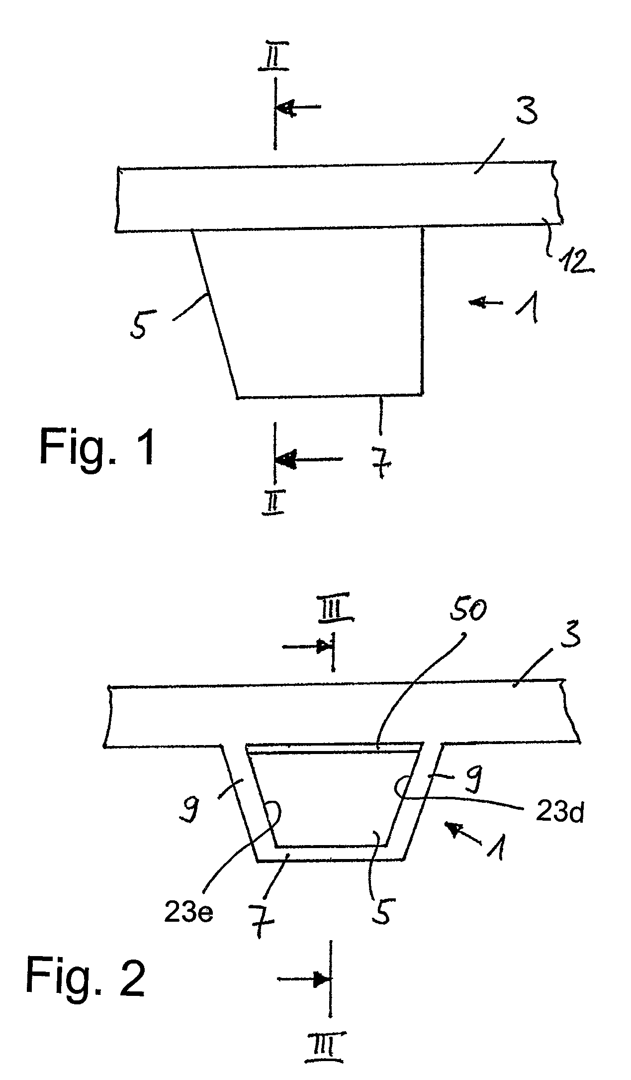
[0022]According to the production method, the additional molded part can be at least an attachment or a structural element that projects from the backing layer or a rod-shaped structure. Moreover, the additional molded part can be a holder for receiving components or other parts. Furthermore, the additional molded part can be a connecting element or a rib or a spacing element or a design element for improving the strength of the component.
[0025]The cavity and the slider can be constructed in such a manner that the attachment is at least one structural element, which projects from the component, or a rod-shaped structure. Moreover, the cavity and the slider can be constructed in such a manner that the attachment is a holder for receiving components or other parts or also so that the attachment is a connecting element or a rib or a design element for improving the strength of the component.
[0026]One advantage of the inventive solution is that the low injection pressure, which suffices in the inventive method to create attachments, yields large bonding areas or reinforcing elements between the attachment and the backing element. Consequently it is possible to transfer larger forces from the attachment to the backing element. In addition, a deformation of the backing element (that is, markings or curvature) is ruled out, so that the result is a negligible pressure load on the decorative material.
[0027]Since the inventive production of the attachment on the inside of a component takes place when the plastic, e.g. the polypropylene, is injected into the appropriate cavity at low pressure, there is no risk that markings will form on the outside of the component. Therefore, this feature is especially advantageous, because this side of the component is usually its exposed side. Thus, it is possible to achieve with high reliability a smooth surface on the outside or the exposed side.

Problems solved by technology

However, this method is suitable only for simply shaped molded parts.
However, this measure has proved to be very disadvantageous because it leads to wrinkling and damage to the decorative surface.
Furthermore, the decorative layer is pressed so flat that a decorative embossing is no longer possible.
One drawback with this method is that the wall thickness of the attachment is relatively low at the transition region to the backing element so that, as a result the bonding area at this point is negligible.
Furthermore, at a high injection pressure marks form on that side of the backing element and / or the fiber mat that is opposite the side of the attachment owing to the softness of the component.
This side is usually covered with decorative material so that these marks constitute a drawback for the aesthetic appearance.

Method used


Image

  • Method and tool for producing a plastic component with a decorative layer, a backing layer and an additional molded part attached thereto
  • Method and tool for producing a plastic component with a decorative layer, a backing layer and an additional molded part attached thereto
  • Method and tool for producing a plastic component with a decorative layer, a backing layer and an additional molded part attached thereto

Examples


Embodiment Construction

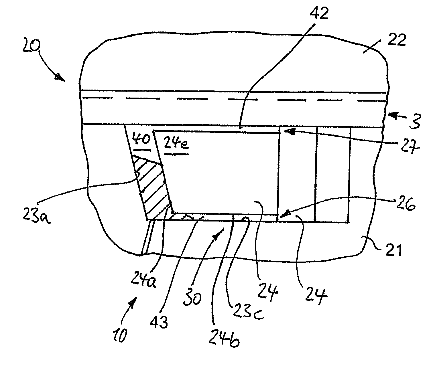
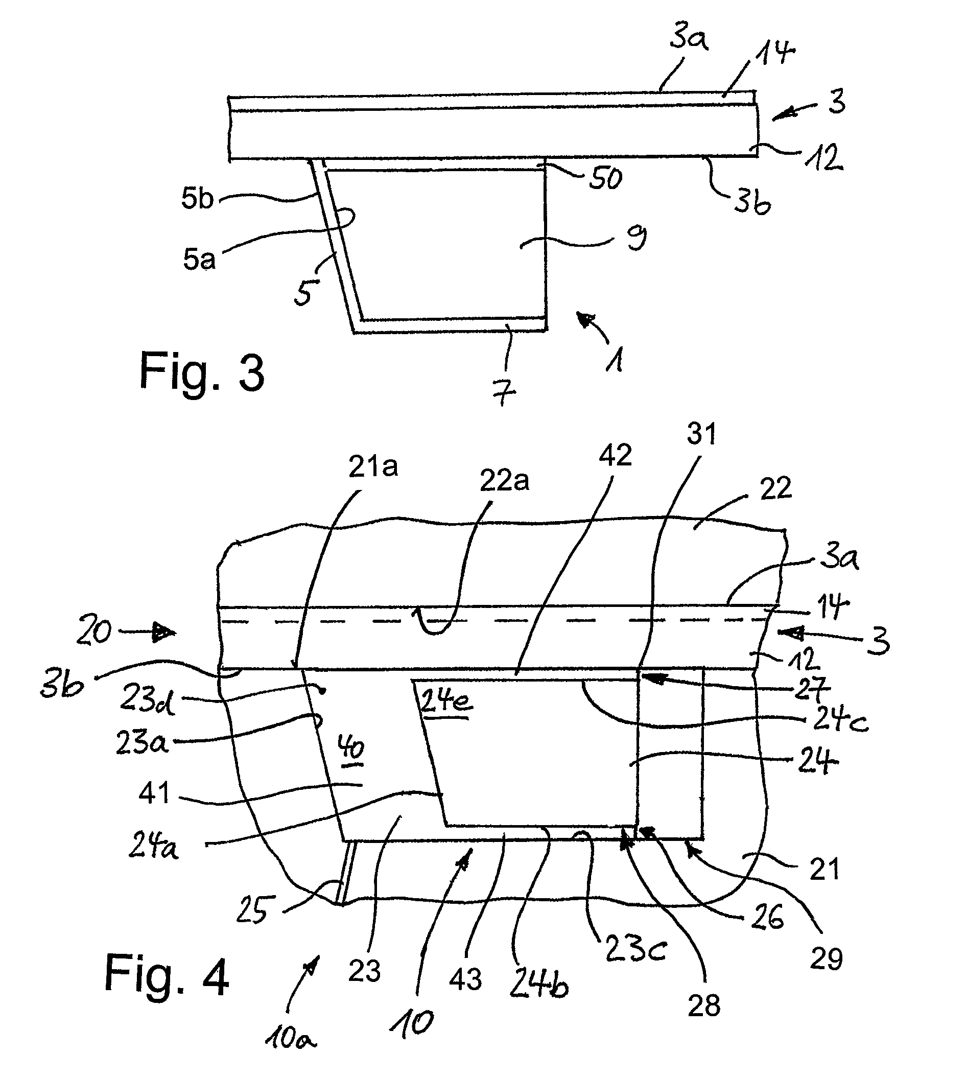
[0039]According to the inventive method, a compression molding process is carried out by a compression molding tool in order to form a combination comprising a backing layer and a decorative layer. The compression molding process is combined with a low pressure injection process in which plastic is fed at a relatively low pressure into a cavity with a slider element, which moves in said cavity in order to form the additional molded part without having to fill this cavity in its entirety. The contour-shaping step takes place with a suitable movement of the slider. Correspondingly, the inventive device for producing a plastic component comprising a decorative layer and a backing layer and an additional molded part relates to a compression molding tool which additionally comprises a cavity with a slider element.

[0040]Therefore, the component is made of a material for a decorative layer 14 in the form of a blank made of a suitable starting material, and a material for a backing layer 12...


PUM

PropertyMeasurementUnit
Temperatureaaaaaaaaaa

Abstract

A method for producing a component (3) comprising a backing layer, a decorative layer and an additional molded part (1) attached to the component. The method includes the following steps: A plasticized mat comprising fiber fractions, which is a starting material for the backing layer (12), is introduced together with a blank, which is a starting material for the decorative layer (14), into a compression molding tool (20) composed of a first tool half (21) including a low pressure injection unit (10) for producing the additional molded part and a second tool half (22). The tool halves (21, 22) are pressed together to join the starting materials; a predetermined quantity of plastic in a fluid state is simultaneously or subsequently introduced into the cavity (23) of the compression molding tool through a supply conduit (25), and a slider (24) is thereafter extended to an end position inside the cavity (23). After cooling of the plastic, the slider is retracted to its starting position, and the tool halves are separated. The invention also includes an apparatus for carrying out the method.

Description

BACKGROUND OF THE INVENTION[0001]The invention relates to a method and a tool for producing a plastic component comprising a decorative layer and a backing layer and an additional molded part.[0002]The component to be produced is, in particular, a plastic component comprising fiber fractions.[0003]The additional molded part is attached to the rest of the component that is produced; and it is defined below, in particular, as an attachment, a retainer element, a receiving element, a reinforcing element or a rib or also, in general, as an additional component, which is to be integrated on the back side of the component.[0004]In the prior art production of plastic components comprising a plurality of layers and additional molded parts, which are attached to said plastic components, the first step is to produce the component, comprising a backing layer and a decorative layer, with a compression molding tool in a laminating and contour-shaping process. In a second step the additional mold...

Claims


Application Information

Patent Timeline
IPC IPC(8): B29C45/56
CPCB29C43/146B29C43/203B29C45/14786B29C45/561B29C45/14811B29L2031/3041B29C2045/0093B29C2045/5635B29L2031/3005
Inventor SCHILLES, WILFRIED
Owner FAURECIA INNENRAUM SYST
Learn More