
Drill template arrangement

a template arrangement and drill technology, applied in the field of drill template arrangement, can solve the problems of high risk of drill direction being wrong and drill penetration through sensitive parts of the eye or orbital cavity, and achieve the effect of avoiding damage risks, reducing the risk of drilling holes, and being easy to maneuver by hand

Active Publication Date: 2011-05-17
NOBEL BIOCARE SERVICES AG
View PDF8 Cites 44 Cited by
  • Summary
  • Abstract
  • Description
  • Claims
  • Application Information

AI Technical Summary

Benefits of technology

This arrangement enables efficient and precise hole formation, reducing the risk of damage to sensitive areas by ensuring accurate drill direction and allowing for flexible use of known components, thereby enhancing safety and precision in dental procedures.

Problems solved by technology

Incorrect handling and incorrect equipment can mean deviations from the drill direction defined with precision in the computer-aided equipment, which means there may be a high risk of the drill direction being wrong and of the drill penetrating through sensitive parts of the eye or orbital cavity.

Method used


Image

  • Drill template arrangement
  • Drill template arrangement
  • Drill template arrangement

Examples


Embodiment Construction

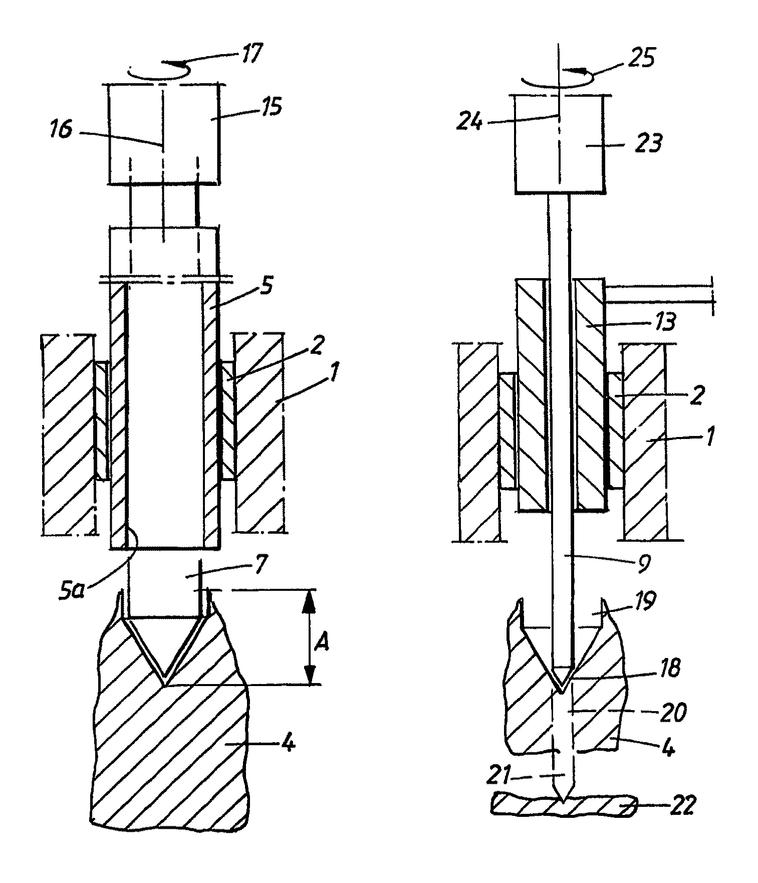
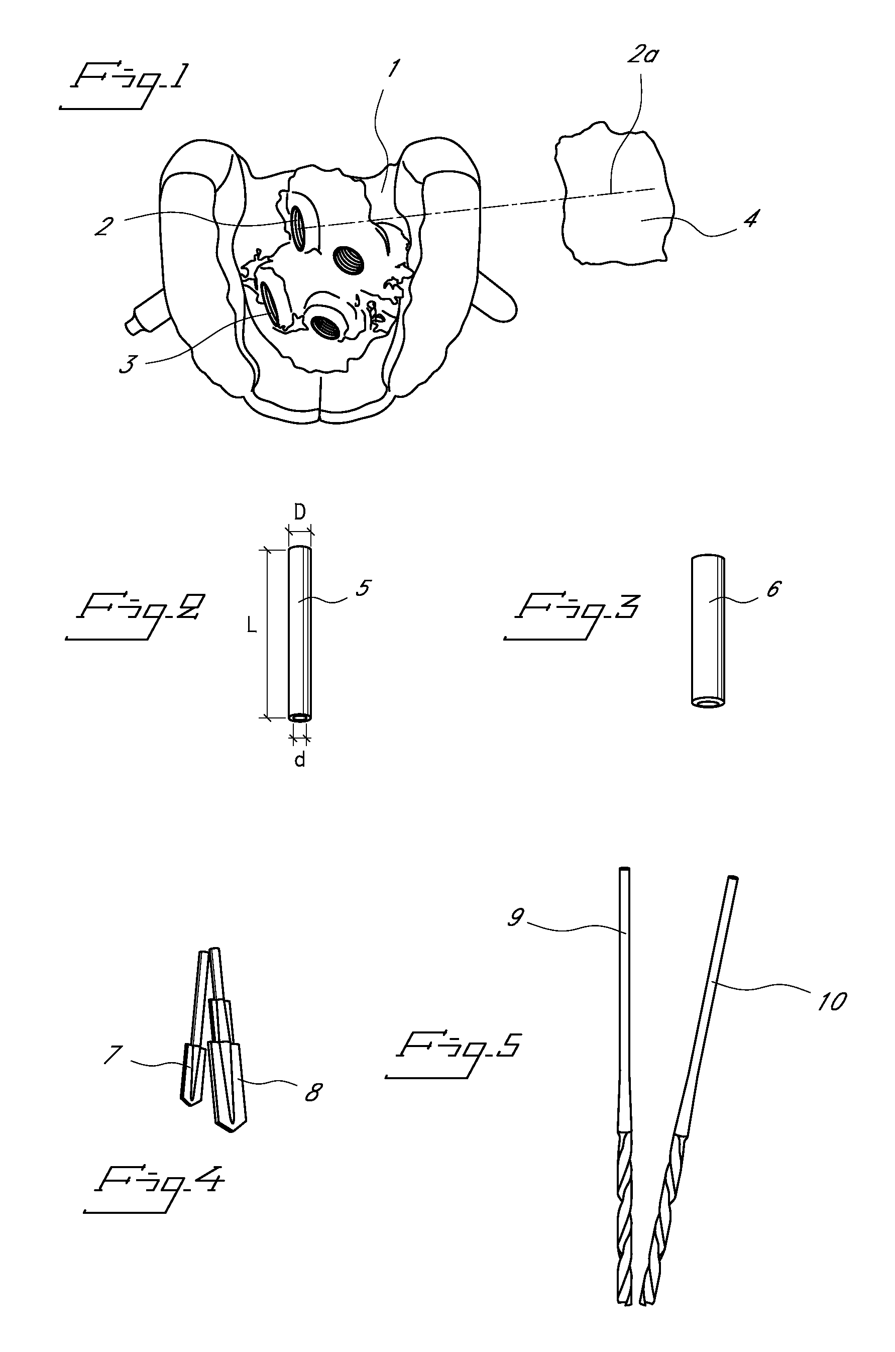
[0025]In FIG. 1, a drill template is indicated by 1. The drill template has guide sleeves 2, 3 which are applied with the aid of computer-aided equipment (not shown). The longitudinal axes of the guide sleeves, for example, a longitudinal axis 2a of the guide sleeve 2, are directed toward a solid part of a symbolically indicated zygoma 4. In the present case, the template has two guide sleeves which are directed toward said zygoma part 4 on one side of the zygoma. A corresponding arrangement with two guide sleeves can be present for alignment with the other side of the zygoma.

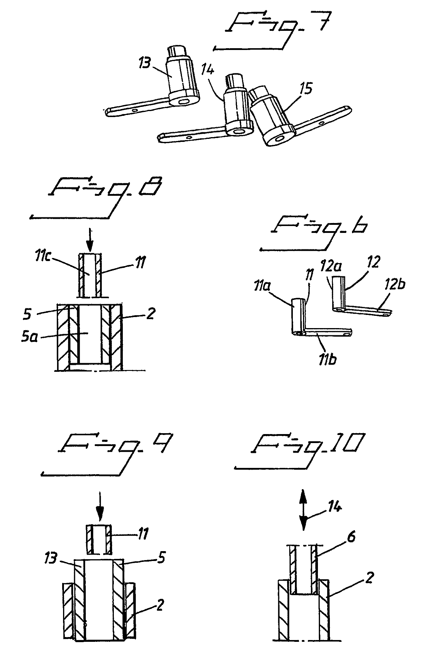
[0026]FIG. 2 shows a cylindrical extension unit 5 from the side. The cylindrical unit 5 has an external diameter D and an internal diameter d and is thus provided with an internal central hole (not shown in FIG. 2) extending in the longitudinal direction of the cylinder. The unit 5 has a length L. In some embodiments, the length can be approximately 30 mm. The diameter D can be approximately 6 mm, and the inter...


PUM


Abstract

A drilling assembly is provided for drilling a hole into a zygoma of a patient. The assembly can comprise a template, an extension unit, a drill guide unit, and first and second drills. The template can be configured for orientation within a patient's mouth and can comprise a guide sleeve having a longitudinal axis extending towards the zygoma when fitted on the patient. The extension unit can include a central bore and be slideably received within the guide sleeve. The drill guide unit can also include a central bore of a different diameter than that of the extension unit. The first drill can be slideably received within the central bore of the guide sleeve. The second drill can have an outer diameter different than that of the first drill and can be configured to be slideably received with the central bore of the drill guide unit.

Description

PRIORITY INFORMATION[0001]This application is a U.S. National Phase of International Application No. PCT / SE2006 / 000541, filed May 5, 2006, which claims priority to Swedish Patent Application No. SE 0501285-1, filed Jun. 3, 2005, each of which is hereby incorporated by reference in its entirety.BACKGROUND[0002]1. Field of the Invention[0003]The present invention relates to an arrangement used on a drill template oriented in the mouth for forming holes intended to extend from the template and into the zygoma. The template in this case can comprise one or more guide sleeves which define the direction toward the zygoma.[0004]2. Description of the Related Art[0005]Various guide arrangements for guiding drills are already known in dentistry. Special care must be taken when forming holes for implants and screws which are to extend into and be anchored in the zygoma.SUMMARY OF THE INVENTION[0006]According to at least one of the embodiments herein is the realization that special problems may...

Claims


Application Information

Patent Timeline
Patent Type & Authority Patents(United States)
IPC IPC(8): A61C1/08
CPCA61C1/084A61C1/082A61C3/02A61C8/0089
Inventor BRAJNOVIC, IZIDORPETTERSSON, ANDREAS
Owner NOBEL BIOCARE SERVICES AG
Learn More