Shared frequency transmitter
a frequency transmitter and frequency technology, applied in the field of shared frequency transmitters, can solve the problem of 1/n-time decrease in frequency use efficiency per system, and achieve the effect of effectively removing interference between systems and improving frequency use efficiency
- Summary
- Abstract
- Description
- Claims
- Application Information
AI Technical Summary
Benefits of technology
Problems solved by technology
Method used
Image
Examples
first embodiment
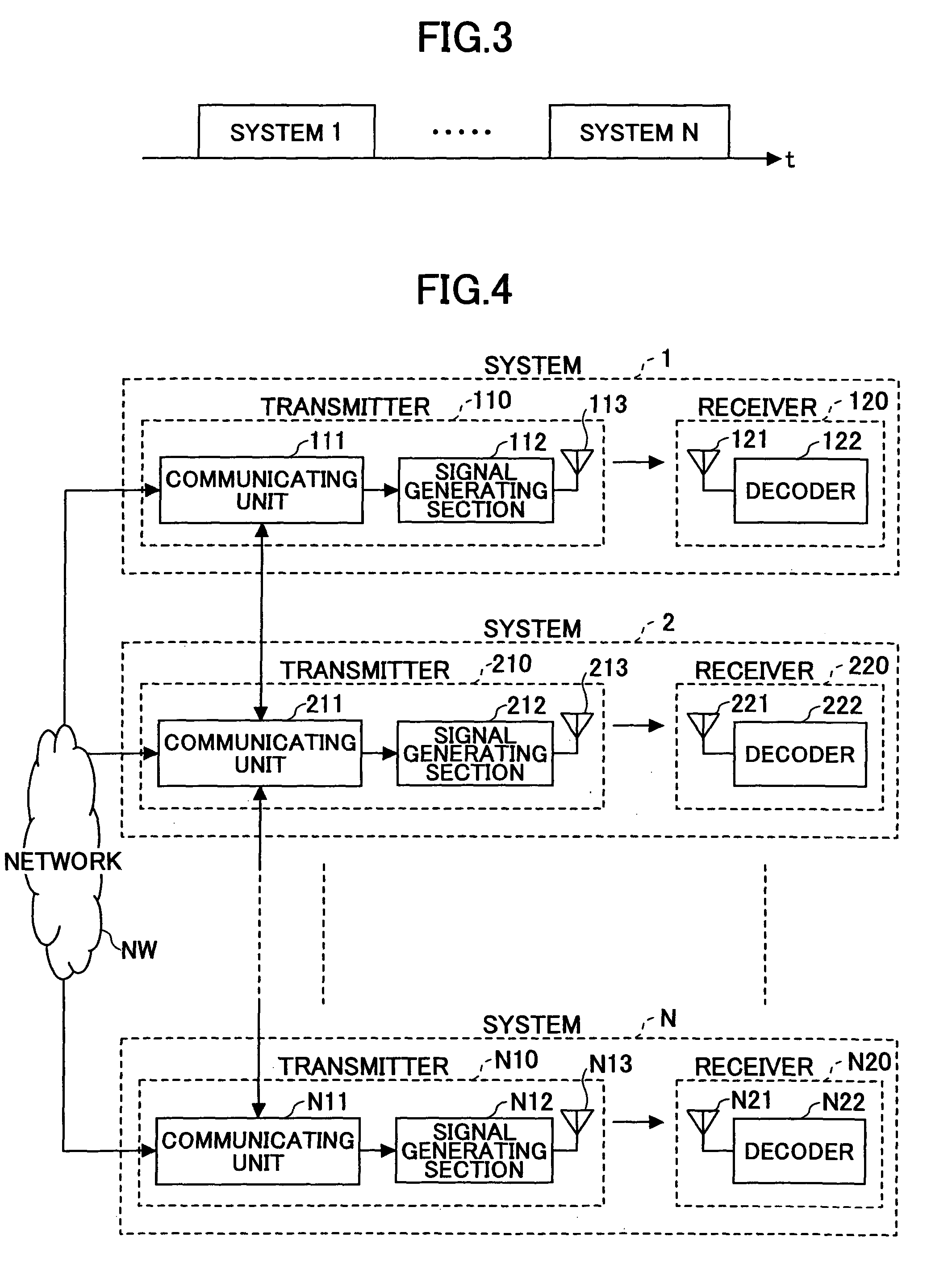
[0052]FIG. 4 is a diagram showing an example of a configuration of transmitters and receivers under the circumstance where plural systems coexist, according to the present invention. In FIG. 4, systems 1, 2 . . . N indicate wireless communication systems provided by different wireless LAN enterprises using the same frequency band. The respective systems 1, 2 . . . N are provided with transmitters 110, 210 . . . N10 connected to a wired network NW such as the Internet, and receivers 120, 220 . . . N20 opposed to these transmitters, respectively. The respective transmitters 110, 210 . . . N10 are provided with communicating units 111, 211 . . . N11 having functions of detecting (searching for) peripheral transmitters in a peripheral area and communicating with the detected peripheral transmitters to exchange information, signal generating units 112, 212 . . . N12 configured to generate transmit signals by applying an interference cancellation technique based on the information obtaine...
second embodiment
[0083]FIG. 11 is a diagram of the configuration according to the present invention, in which radio communication such as Bluetooth communication is used as a communicating function of the communicating units 111, 211 . . . of the transmitters 110, 210 . . . of the systems 1, 2 . . . . It is noted that the configuration of the receiver is omitted in the drawing; however, the remaining part is the same as shown in FIG. 4.
[0084]The second embodiment is suited for the case where the transmitters 110, 210 . . . of the systems 1, 2 . . . are located at a short distance from each other. It is noted that infrared communication other than Bluetooth communication can be used.
third embodiment
[0085]FIG. 12 is a diagram of the configuration according to the present invention, in which wired communication via a router R is used as a communicating function of the communicating units 111, 211 . . . of the transmitters 110, 210 . . . of the systems 1, 2 . . . . It is noted that the configuration of the receiver is omitted in the drawing; however, the remaining part is the same as shown in FIG. 4.
[0086]In the third embodiment, the transmitters 110, 210 . . . of the systems 1, 2 . . . perform packet communication by wired communication link. Thus, the third embodiment is applicable in the case where the transmitters 110, 210 . . . of the systems 1, 2 . . . are not located at a short distance from each other.
PUM
 Abstract
Description
Claims
Application Information
 - R&D
- Intellectual Property
- Life Sciences
- Materials
- Tech Scout
- Unparalleled Data Quality
- Higher Quality Content
- 60% Fewer Hallucinations
Browse by: Latest US Patents, China's latest patents, Technical Efficacy Thesaurus, Application Domain, Technology Topic, Popular Technical Reports.
© 2025 PatSnap. All rights reserved.Legal|Privacy policy|Modern Slavery Act Transparency Statement|Sitemap|About US| Contact US: help@patsnap.com


