Optical disk for an identification element

a technology of optical disks and identification elements, applied in the field of optical disks, can solve the problems of paper layer not serving to stiffen the layer of aluminum, and achieve the effects of reducing the risk of optical disks being reproduced, combating counterfeiting of audiovisuals, and reducing the risk of optical disks

Inactive Publication Date: 2011-05-03
ARJO WIGGINS SECURITY SAS
View PDF20 Cites 6 Cited by
  • Summary
  • Abstract
  • Description
  • Claims
  • Application Information

AI Technical Summary

Benefits of technology

The patent aims to reduce the risk of illegal reproduction of optical disks and prevent counterfeiting of audiovisual and software works.

Problems solved by technology

The patent text discusses optical disks and how they can be used to store information that can be read by a laser while the disk is rotating. The technical problem addressed in the patent text is how to provide a flexible structure for the optical disk that can be stiffened while also allowing for the storage of data using a chip and layer of aluminum.

Method used


Image

  • Optical disk for an identification element
  • Optical disk for an identification element
  • Optical disk for an identification element

Examples


Embodiment Construction

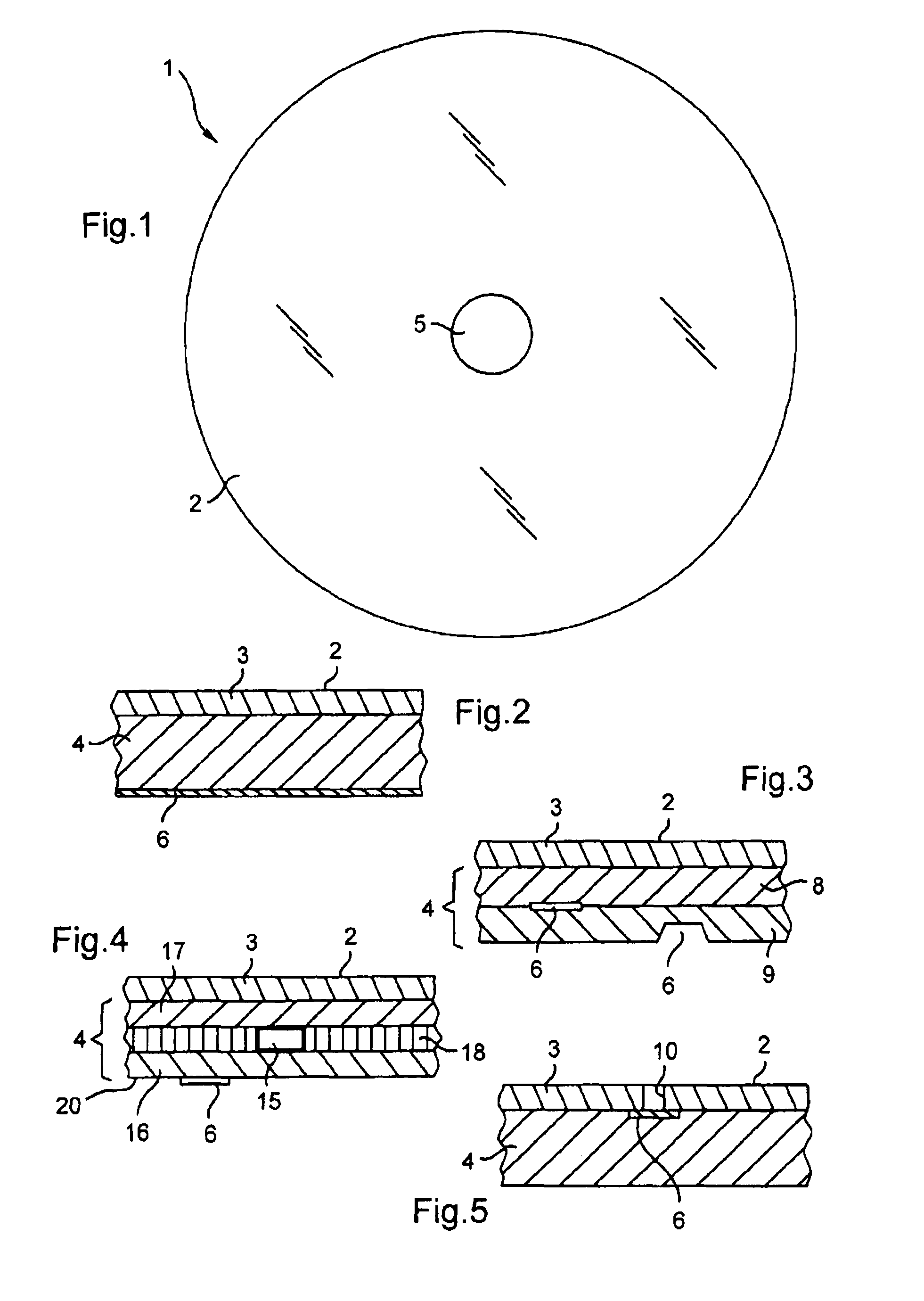
The disk 1 shown in FIG. 1 presents a face 2 carrying data that can be read by a laser while the disk is being driven in rotation, e.g. a laser that emits in the blue (Blue-Ray Disc Technology).

The face 2 is defined by a flexible structure 3 secured to a support 4 serving to stiffen it, as can be seen in FIG. 2.

By way of example, the disk 1 is circular in shape having a hole 5 at its center for engaging means for centering and rotating the disk. In a variant, the disk presents an outline that is not circular, e.g. presenting a credit card format.

In accordance with an aspect of the invention, the support 4 has at least one fiber layer which may include at least one authentication and / or identification element 6, which element may be inside and / or outside the fiber layer 4.

By way of example the layer may be made of paper or card.

In the example of FIG. 2, the element 6 is constituted, for example, by printing using an ink, in particular an ink that is magnetic, thermochromic, fluoresce...


PUM


Abstract

An optical disk is provided that includes a face carrying information that is readable by a laser while the disk is being driven in rotation, the face being defined by a flexible structure; a support stiffening the flexible structure and including at least one fiber layer having a thickness; and an identification and/or authentication element carried by the support, the identification and/or authentication element being configured to emit a detectable signal on being illuminated by the laser that is used for reading the information present on the face, the identification and/or authentication element being inside and/or outside the support.

Description


Claims


Application Information

Patent Timeline
Owner ARJO WIGGINS SECURITY SAS
Why Eureka
Try Eureka