
Binding to business objects and web services

a business object and web service technology, applied in the field of software development tools, can solve the problems of limited design-time support, inordinate amount of learning and struggling with the development environment, and the addition of these base class(es) and/or interfaces is time-consuming and adds limited, if any, value, etc., to facilitate entity data binding

Inactive Publication Date: 2011-04-12
MICROSOFT TECH LICENSING LLC
View PDF18 Cites 80 Cited by
  • Summary
  • Abstract
  • Description
  • Claims
  • Application Information

AI Technical Summary

Benefits of technology

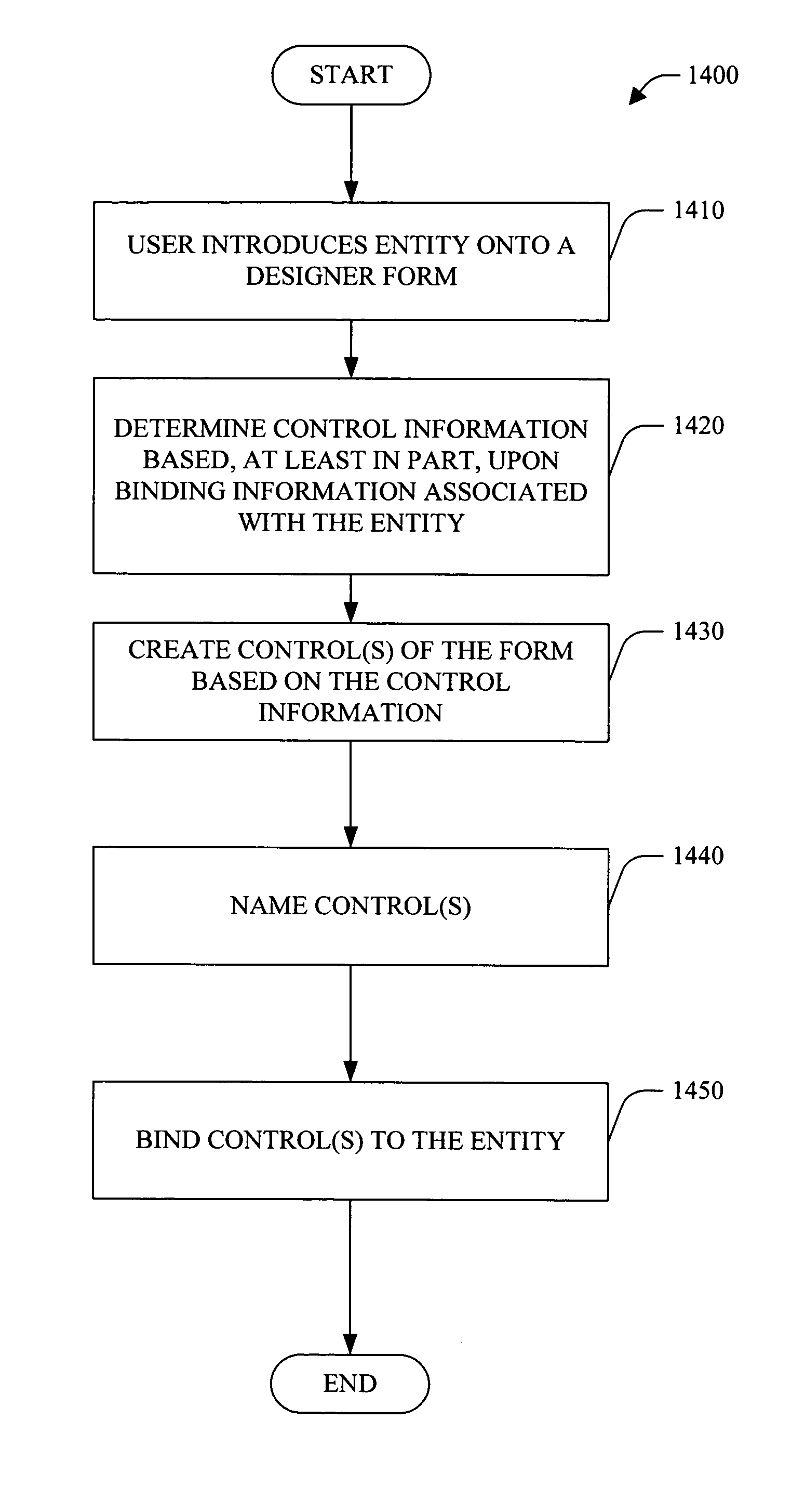
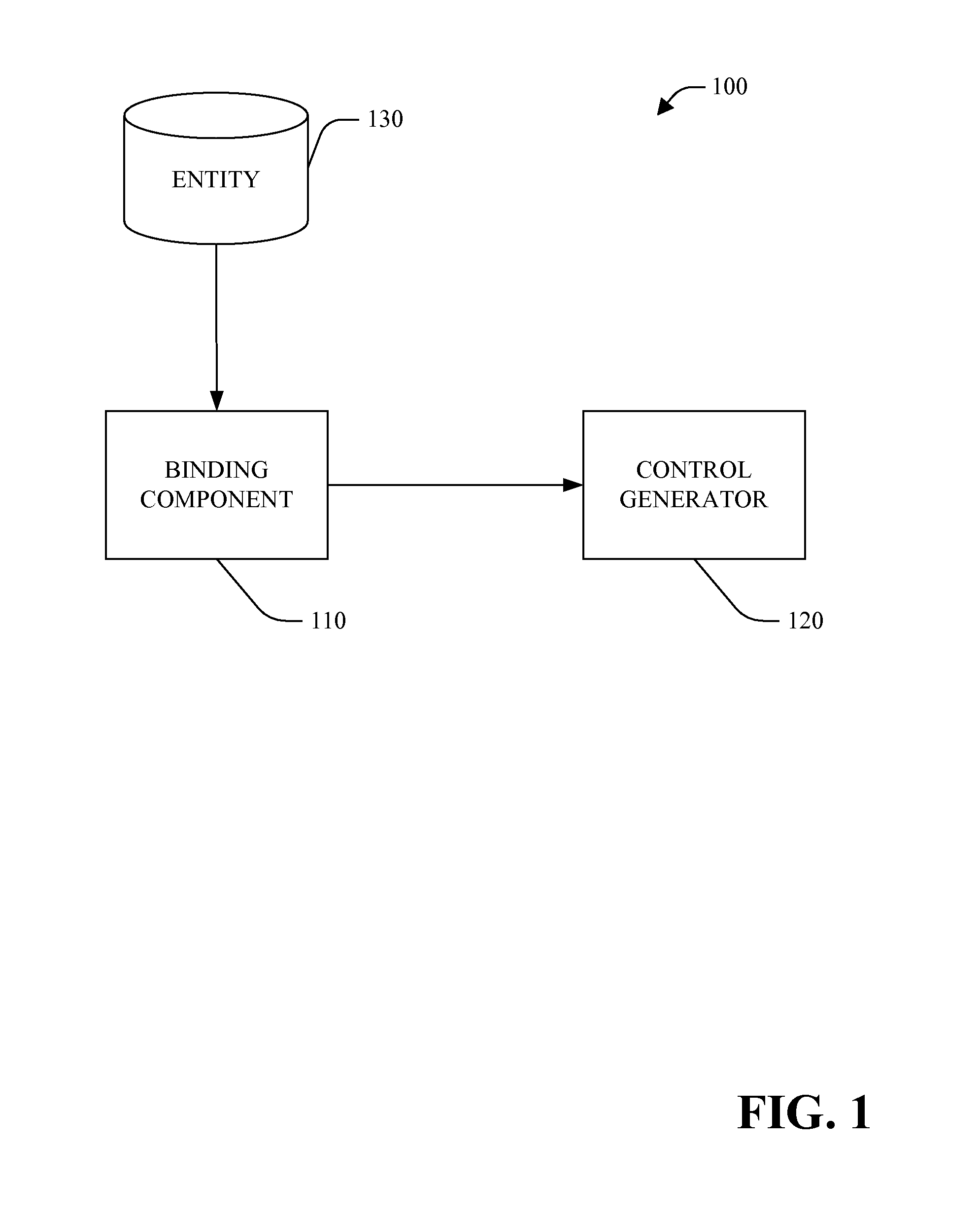
The subject invention is a system and method that allows developers to easily bind data to business objects and web services during design-time. The system generates control information based on the binding information of the entity and creates the associated relationship on the form. This allows developers to drag and modify objects on the form without needing specific inheritance, interface implementation, or default public constructors. The system also captures the hierarchy of the object and allows developers to update related lists. Overall, the subject invention simplifies data binding and improves efficiency for developers.

Problems solved by technology

However, the rapid evolution in which such development frameworks are manufactured and sold impact the speed with which such tools can be understood and used to provide the software for which they are created.
Developers are still left spending an inordinate amount of time learning and struggling with the development environment in order to provide a suitable product for a customer.
Conventional development tools have supported data binding to object(s); however, there was limited design-time support.
The addition of these base class(es) and / or interface(s) was time-consuming and added limited, if any, value at run-time.

Method used


Image

  • Binding to business objects and web services
  • Binding to business objects and web services
  • Binding to business objects and web services

Examples


Embodiment Construction

[0026]The subject invention is now described with reference to the drawings, wherein like reference numerals are used to refer to like elements throughout. In the following description, for purposes of explanation, numerous specific details are set forth in order to provide a thorough understanding of the subject invention. It may be evident, however, that the subject invention may be practiced without these specific details. In other instances, well-known structures and devices are shown in block diagram form in order to facilitate describing the subject invention.

[0027]As used in this application, the terms “component,”“handler,”“model,”“system,” and the like are intended to refer to a computer-related entity, either hardware, a combination of hardware and software, software, or software in execution. For example, a component may be, but is not limited to being, a process running on a processor, a processor, an object, an executable, a thread of execution, a program, and / or a comp...


PUM


Abstract

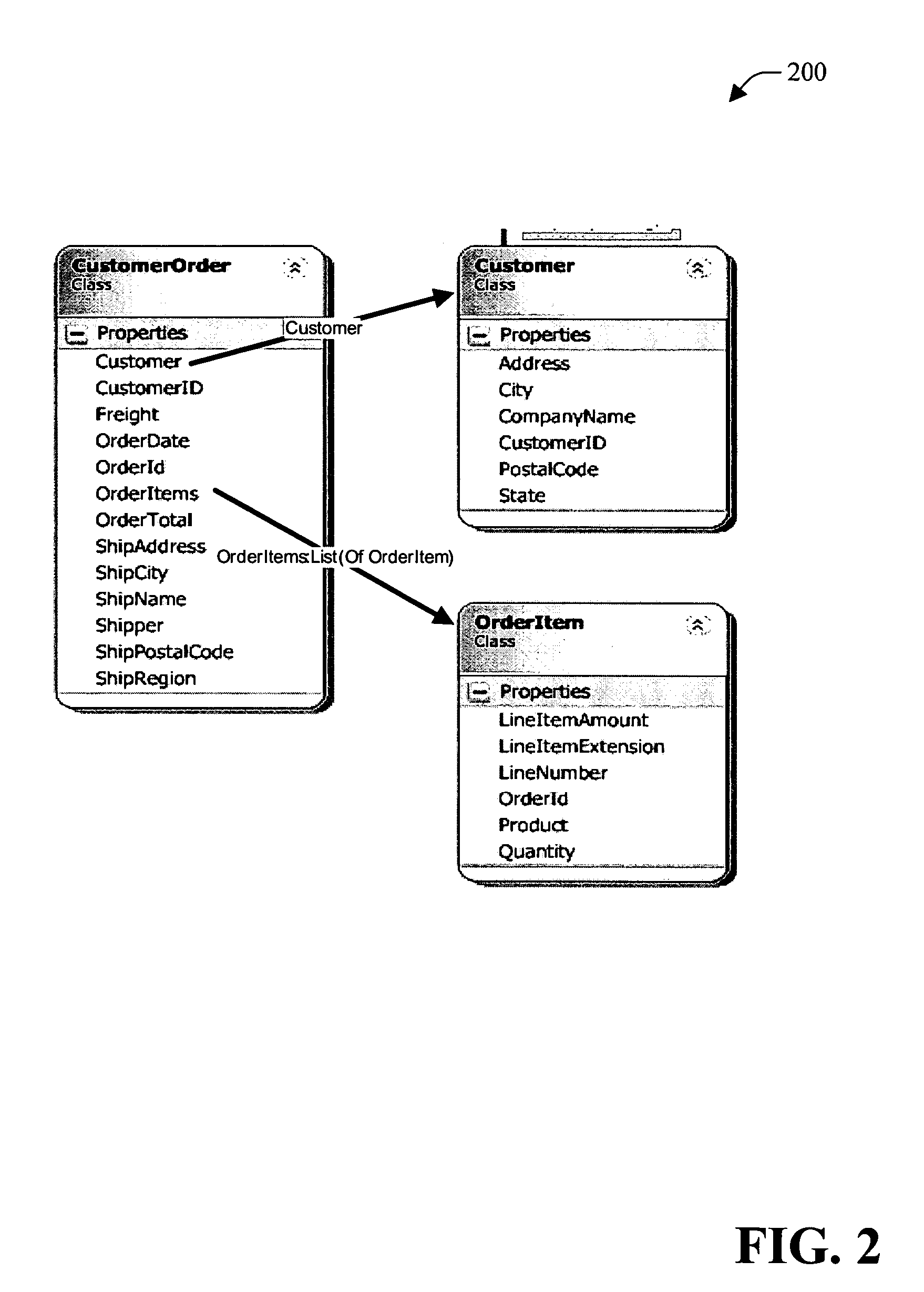
A system and method for method facilitating design-time data binding of business object(s) and / or web service(s) is provided. Developer(s) can specify their own class(es) that do not require specific inheritance, interface implementation or default public constructors.The system includes a binding component that generates control information associated with control(s) based, at least in part, upon binding information associated with an entity (e.g., object, business object and / or web service). The system further includes a control generator that generates control(s) of a form associated with the entity based upon the generated by the binding component.The binding component can utilize public property(ies) of the entity (e.g., object, business object and / or web service). The entity can represent a hierarchy of objects that drill down (e.g., endlessly), including circular relationships.At design-time, a user (e.g., developer) can drag the root of an object (e.g., a business object and / or a web service) onto a form. Control(s) associated with the form are created by the system based on a schema of the object.

Description

TECHNICAL FIELD[0001]The subject invention relates generally to software development tools, and more specifically, to a system for data binding business object(s) and / or web service(s).BACKGROUND OF THE INVENTION[0002]Software vendors are continually advancing the latest in development tools for users to take advantage of software made available to consumers. Typically, such tools require some level of familiarity by developer with the tool(s) language and structure in order to use the development tool(s) and develop the appropriate interface. However, the rapid evolution in which such development frameworks are manufactured and sold impact the speed with which such tools can be understood and used to provide the software for which they are created. Developers are still left spending an inordinate amount of time learning and struggling with the development environment in order to provide a suitable product for a customer.[0003]Conventional development tools have supported data bindi...

Claims


Application Information

Patent Timeline
Patent Type & Authority Patents(United States)
IPC IPC(8): G06F9/44
CPCG06Q10/10
Inventor CHEN, JOHN ZSTEGMAN, JOSEPH PZADORA-PRZYLECKI, KAROLLASKER, STEVEN M
Owner MICROSOFT TECH LICENSING LLC
Learn More