Faraday rotator mirror and method for manufacturing the same
a technology of rotator mirror and rotator blade, which is applied in the field of faraday rotator mirror, can solve the problems of fluctuation of output, deterioration of signal waveform, and fluctuation of state of polarization, so as to achieve easy manufacturing of high coupling efficiency, suppress moisture, and suppress characteristics of insertion loss
- Summary
- Abstract
- Description
- Claims
- Application Information
AI Technical Summary
Benefits of technology
Problems solved by technology
Method used
Image
Examples
first embodiment
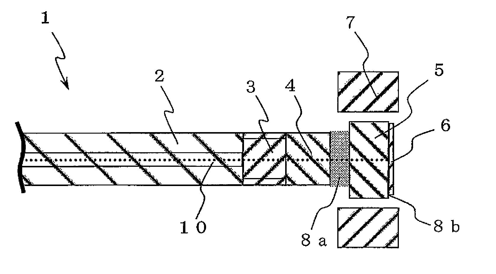
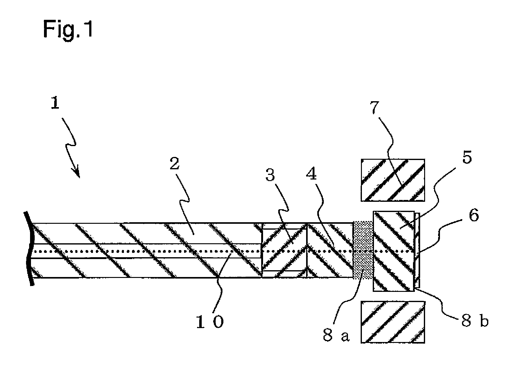
[0091]FIG. 1 is a sectional view schematically showing the constitution of a Faraday rotator mirror 1 according to the first embodiment of the present invention. The Faraday rotator mirror 1 comprises a single mode fiber 2, a graded-index fiber (GIF) 3, a coreless fiber 4, a Faraday rotator 5, a reflector mirror 6, the magnet 7 and optically compatible adhesives 8a, 8b.
[0092]The optical fiber 2 is for guiding light incident on one end thereof and letting the light emerge from the other end. The optical fiber 2 may be formed from quartz glass, multiple-component glass, plastics or the like.
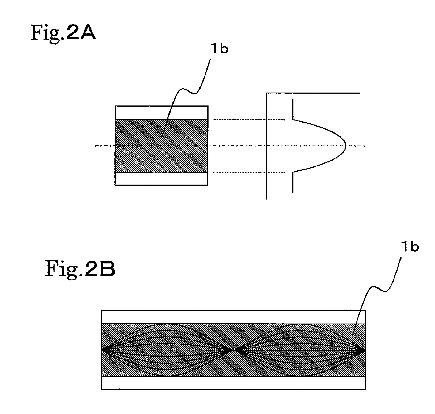
[0093]The graded-index fiber 3 is an optical fiber which has such a refractive index distribution that decreases stepwise or continuously from the center toward the circumference as shown in FIG. 2A, so that a light ray which passes through the fiber meanders periodically as shown in FIG. 2B. Therefore, light ray can be converged or collimated so that the fiber functions as a lens, by cutting the ...
second embodiment
[0115]FIG. 5 is a sectional view schematically showing the constitution of the Faraday rotator mirror 11 according to the second embodiment of the present invention.
[0116]The Faraday rotator mirror 11 of the second embodiment is different from the Faraday rotator mirror 1 of the first embodiment in the following points.
[0117](1) An end face of the coreless fiber 4 which opposes the Faraday rotator 5 is tilted from the plane perpendicular to the optical axis 10, and the Faraday rotator 5 is put into contact with the tilted face of the coreless fiber 4 via the optically compatible adhesive 8a.
[0118]As a result, the Faraday rotator 5 is also tilted from the plane perpendicular to the optical axis 10.
[0119](2) The optically compatible adhesive 8b is formed in wedge shape so as to dispose the reflector mirror 6 so that the principal surface (reflecting surface) thereof is perpendicular to the optical axis 10, and variations in machining of the graded-index fiber 3 and other component ar...
third embodiment
[0122]FIG. 7 is a sectional view schematically showing the constitution of the Faraday rotator mirror 12 according to the third embodiment of the present invention. The Faraday rotator mirror 12 of the third embodiment is constituted similarly to the Faraday rotator mirror 11 of the second embodiment, except that the single mode fiber 2, the graded-index fiber 3 and the coreless fiber 4 are held by a ferrule 13.
[0123]The Faraday rotator mirror 12 can be made structurally stable even when the fibers 2 through 4 have diameters (for example, 125 μm) smaller than the physical thickness (for example, 350 to 500 μm) of the Faraday rotator 5, by adjusting the mounting surface of the Faraday rotator 5 in the ferrule 13 to an optimum size (which is determined according to the physical thickness of the Faraday rotator 5). When forming the tilted surface on the coreless fiber 4 in the Faraday rotator mirror 12, it is possible to polish the coreless fiber 4 together with the ferrule 13, and the...
PUM
| Property | Measurement | Unit |
|---|---|---|
| thickness | aaaaa | aaaaa |
| reflectivity | aaaaa | aaaaa |
| diameter | aaaaa | aaaaa |
Abstract
Description
Claims
Application Information
 - R&D
- Intellectual Property
- Life Sciences
- Materials
- Tech Scout
- Unparalleled Data Quality
- Higher Quality Content
- 60% Fewer Hallucinations
Browse by: Latest US Patents, China's latest patents, Technical Efficacy Thesaurus, Application Domain, Technology Topic, Popular Technical Reports.
© 2025 PatSnap. All rights reserved.Legal|Privacy policy|Modern Slavery Act Transparency Statement|Sitemap|About US| Contact US: help@patsnap.com


