Plyometric training device and method

a technology of muscle strengthening and training equipment, applied in the field of plyometric muscle strengthening devices and methods, can solve the problems of difficult increase of ability, a risk of injury by the return bar, and the muscle seldom performs one type of contraction in isolation

Active Publication Date: 2011-04-05
LAMARQUE MATTHEW
View PDF11 Cites 6 Cited by
  • Summary
  • Abstract
  • Description
  • Claims
  • Application Information

AI Technical Summary

Benefits of technology

[0008]It is an object of the present invention to provide a method that enables the use of a weight in a plyometric muscular training protocol.
[0009]It is another object of the present invention to provide a device that enables the use of a weight bar in a plyometric muscular training protocol.
[0010]It is an object of certain preferred alternate embodiments of the Method of the Present Invention to provide a limitation to the range of motion of a weighted bar used in a plyometric muscular training protocol.
[0014]The upper cable may be configured to limit the movement range of the weight to restrict the weight from falling below a torso of the subject when the subject is standing and insubstantial contact with a vertical support pad. The vertical pad is sized and shaped to at least partially support the subject's torso in a position that maintains the subject's torso is beyond the movement range of the weight allowed by the upper cable and the front cable.
[0017]The Method of the Present Invention may further provide a method of enabling plyometric muscular training wherein a plyometric training device is provided. A subject is directed to grasp and propel the weight; and the subject is directed to catch the weight as the weight returns towards the subject after the weight is propelled by the subject.

Problems solved by technology

The trainee may thereby be placed in the pathway of the returning bar and can run a risk of injury by the returning bar.
This ability is difficult to increase with conventional peak-contraction training methods wherein the fully contracted muscle is maintained in continuous tension.
Of course, muscles seldom perform one type of contraction in isolation during athletic movements.

Method used


Image

  • Plyometric training device and method
  • Plyometric training device and method
  • Plyometric training device and method

Examples


Embodiment Construction

[0026]In describing the preferred embodiments, certain terminology will be utilized for the sake of clarity. Such terminology is intended to encompass the recited embodiment, as well as all technical equivalents, which operate in a similar manner for a similar purpose to achieve a similar result.

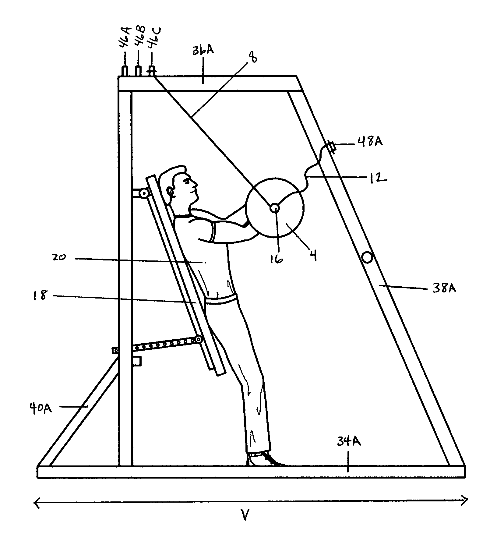
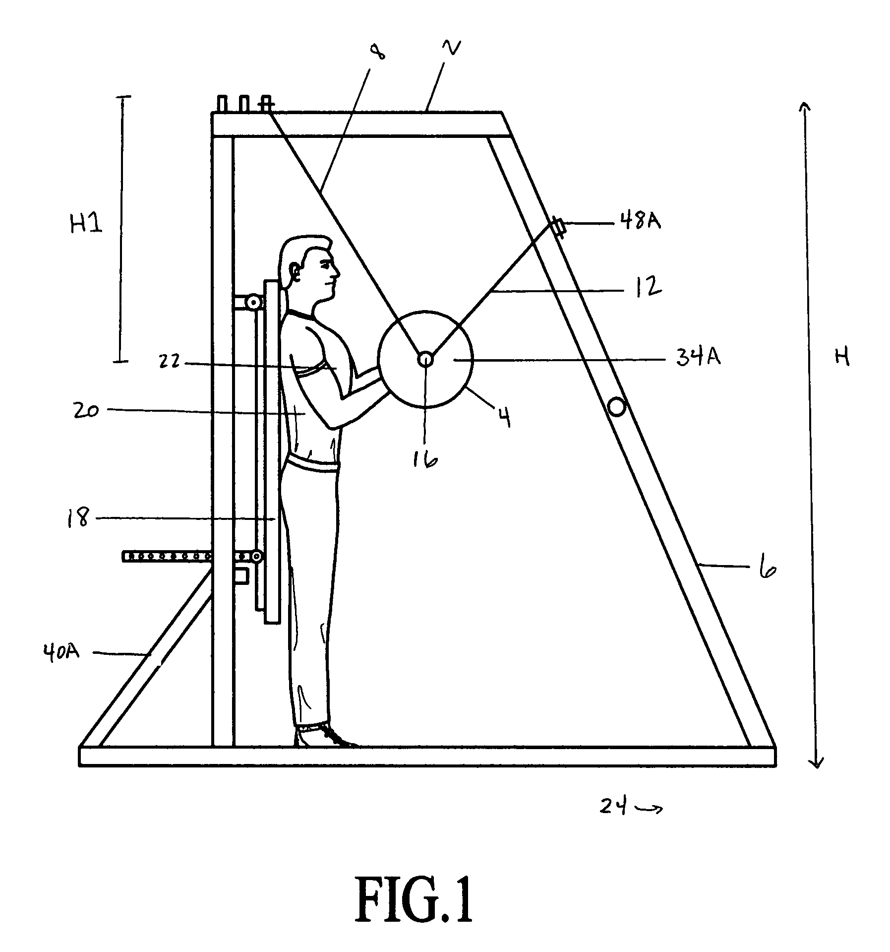
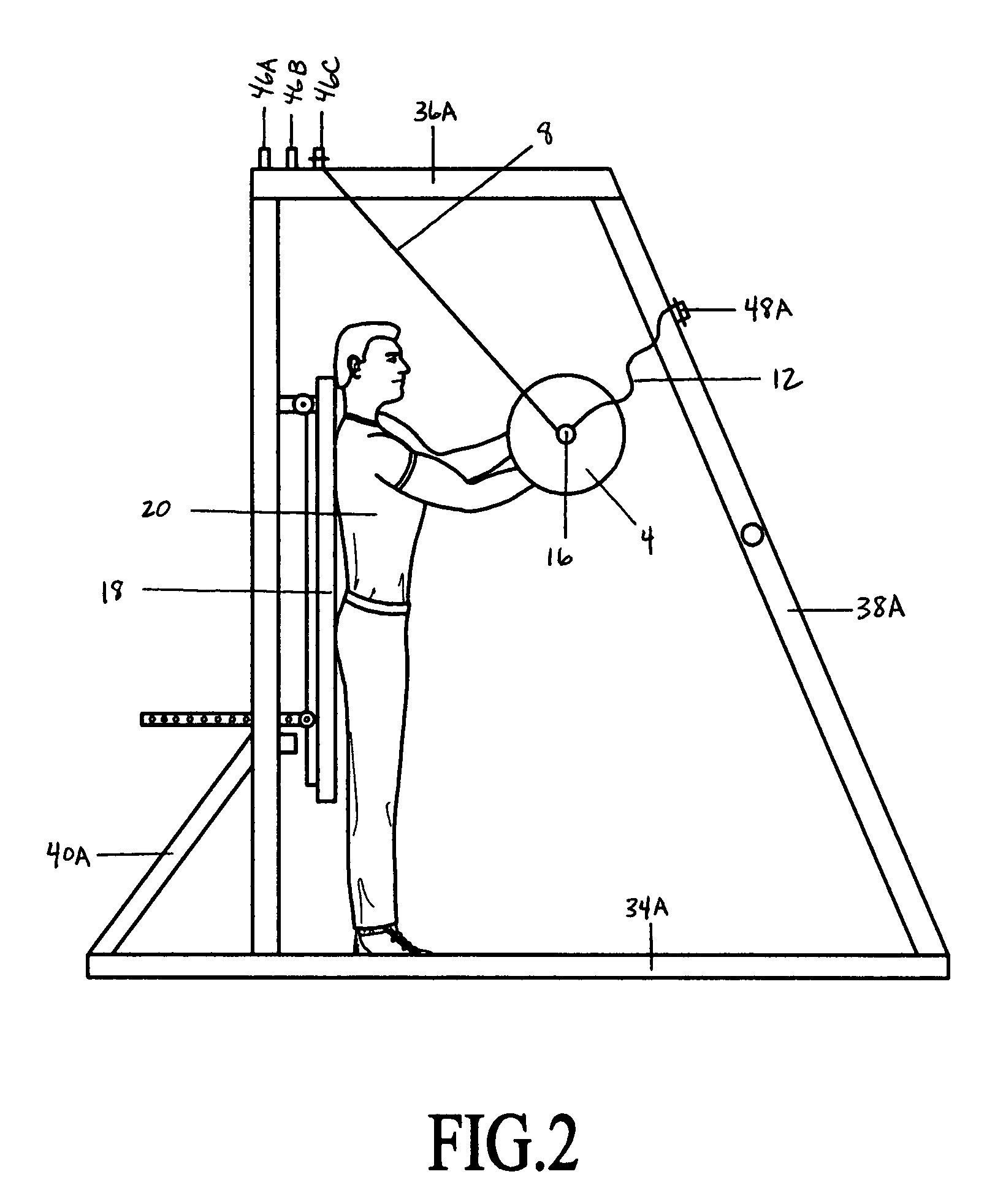
[0027]Referring now generally to the Figures, and particularly to FIG. 1, FIG. 1 shows a first preferred embodiment of the present invention 2, or first version 2, wherein a weight 4 is coupled to a frame 6 by means of a pair of upper cables 8&10 and a pair of front cables 12&14. The range of movement of the weight 4 is restricted by the frame 6 and each of the pair of upper cables 8&10 and the pair of front cables 12&14.

[0028]The weight 4, including a weighted bar 16, a first weight 4A and a second weight 4B, may conform to a published equipment standard for weight lifting competition, such as a standard published by the International Olympic Committee.

[0029]An optional vertical pad 18 may ...


PUM


Abstract

A method and device for use in plyometric muscular training is provided. In a first version, a rigid frame is provided having a trainee's position, a pair of cables and a weighted bar. The cables are positioned between the trainee's position and the bar. Each cable is attached at an upper location and a forward location of the frame. The cables partially constrain the movement of the bar and restrain the bar from striking sections of the trainee's body. The trainee may explosively push or throw the bar away from the trainee's position and towards the cable attachment locations, wherein the bar is released from the trainee's grasp. The return pathway of the bar is determined by the force of gravity, the force provided by the trainee and the constraints of the cables. The cables reduce the risk of injury to the trainee.

Description

FIELD OF THE INVENTION[0001]The present invention is related to plyometric muscle strengthening devices and methods. More particularly the present invention is related to methods and devices for safely applying plyometric techniques.BACKGROUND OF THE INVENTION[0002]Plyometric training techniques often require that a weighted bar be pushed away by a trainee from a starting position as quickly as possible by the trainee. It is sometimes desirable that the trainee push the bar beyond the trainee's grasp; the bar is then typically captured by the trainee in a gravity-directed return movement of the weighted bar toward the starting position. The trainee may thereby be placed in the pathway of the returning bar and can run a risk of injury by the returning bar.[0003]Plyometric muscular training is used to increase absolute muscle strength in numerous physical training and therapeutic programs. In particular, the development of explosive strength affected by plyometric muscular training is...

Claims


Application Information

Patent Timeline
Patent Type & Authority Patents(United States)
IPC IPC(8): A63B21/06A63B21/078
CPCA63B21/00181A63B23/12A63B21/0613A63B2208/0204A63B2021/0612A63B21/072A63B23/03525A63B23/1209A63B21/0622A63B21/0624A63B21/4033A63B21/4035A63B21/4043
Inventor LAMARQUE, MATTHEW
Owner LAMARQUE MATTHEW
Why Eureka
Try Eureka