
Adjustable-length seat post

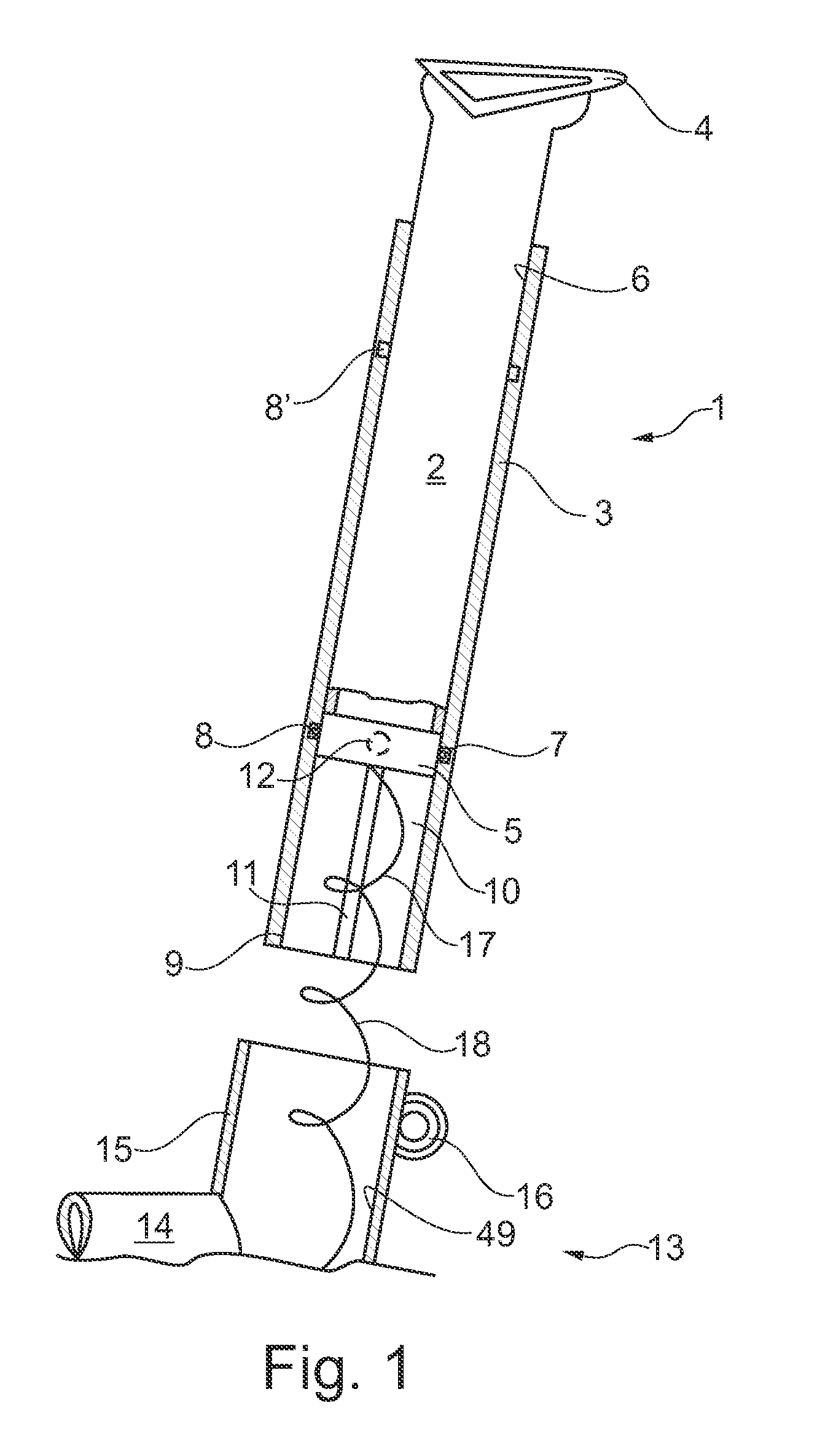
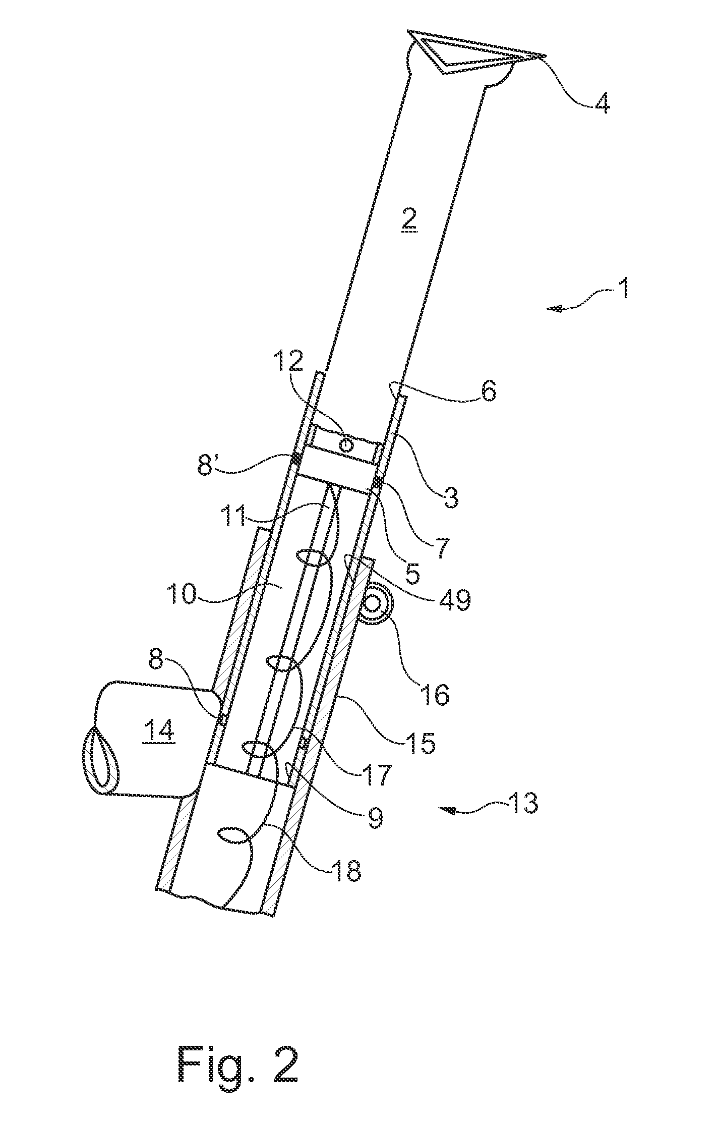
a seat post and adjustable technology, applied in the field of adjustable seat posts for bicycles, can solve the problems of not being able to eliminate the possibility of the rider getting caught on the loop, behind or in front of the saddle,

Inactive Publication Date: 2011-03-22
KLIEBER JOCHEN
View PDF20 Cites 85 Cited by
  • Summary
  • Abstract
  • Description
  • Claims
  • Application Information

AI Technical Summary

Benefits of technology

The solution enables seamless adjustment of the seat post without loop interference, enhancing rider control and safety by maintaining optimal distance settings, allowing for better control during both uphill and downhill riding without the risk of getting caught on the saddle edge.

Problems solved by technology

Synchronising these movement sequences is a major challenge for the coordination capacity of the rider especially as on the one hand he is riding one-handed whilst adjusting the seat post and on the other hand he must concentrate both on the route and also continue to pedal.
The possibility of the rider getting caught on this loop when moving his bottom to counterbalance the bicycle behind or in front of the saddle can no longer be eliminated.

Method used


Image

  • Adjustable-length seat post
  • Adjustable-length seat post
  • Adjustable-length seat post

Examples


second embodiment

[0060]FIG. 4 shows the energy transmission device 17, wherein the energy transmission device 17 is configured here as a limp cable 22. The cable 22 also has a first end 19 and a second end 20. The first end 19 is connected to a servo motor which is flange-mounted to the locking device 5, not shown here. The second end 20 is firmly connected to the seat tube 15. The cable 22 is considerably longer than the distance between the locking device 5 and the fastening on the seat tube 15. The cable 22 is guided over a mandrel 23, which is firmly connected to the seat tube 15, and fastened to the mandrel. The cable 22 thereby forms a first bend 24 which is open towards the second end 20 of the cable 22. The cable 22 furthermore forms a second bend 25 which is open towards the sliding tube 2. If the sliding tube 2 is now shifted along the double arrow 21 in the stanchion 3, a distance X between the second bend 25 and the mandrel 23 changes. Of course, the cable 22 can also be guided in a prot...

fourth embodiment

[0062]FIG. 6 shows the energy transmission device 17. The energy transmission device 17 consists of a rotary bar 29 which is connected by its one end 19 to the locking device 5 and extends in the longitudinal direction of extension of the sliding tube 2, and an entrainer 30. The rotary bar 29 consists of a round rod which has a continuous flattening 31. This is clearly visible in FIG. 7 which shows a cross-section through the rotary bar 29 and a plan view of the entrainer 30. The cross-section through the rotary bar 29 is shown hatched.

[0063]The entrainer 30 is fastened in the seat tube 15 in such a manner that it can turn but is invariant in height relative to the seat tube 15. The rotary bar 29 is displaceable along its longitudinal direction of extension relative to the entrainer 30.

[0064]It can also be clearly seen in FIG. 7 that an internal opening 32 of this entrainer 30 has the external contour of the rotary bar 29. In addition, the entrainer 30 has a side arm 33 which is fir...


PUM


Abstract

An adjustable-length seat post has a stanchion with first and second openings. The seat post has a sliding tube, a locking device and an energy transmission device. The sliding tube is guided through the first opening into the stanchion and is displaceable along a longitudinal direction of extension of the stanchion. The sliding tube is movable relative to the stanchion. An overlap between stanchion and sliding tube in a first position is greater than in a second position. The locking device can be transferred between a locking position and a releasing position, wherein in the locking position the sliding tube is fixed. The energy transmission device can transmit energy from an external actuating element to be provided to the locking device for releasing or locking. When the sliding tube is in the second position, the energy transmission device arranged guided from an external actuating element to be supplied through the second opening of the stanchion as far as the locking device.

Description

CROSS-REFERENCE TO RELATED APPLICATIONS[0001]This application claims priority to U.S. Provisional Patent Application No. 61 / 153,678, filed Feb. 19, 2009, entitled, “LONGITUDINALLY ADJUSTABLE SEAT POST,” and to German Patent Application No. 10 2009 009 645.0, filed Feb. 19, 2009, entitled, “LONGITUDINALLY ADJUSTABLE SEAT POST,” both of which are herein incorporated by reference in their entirety.FIELD OF THE INVENTION[0002]The present invention relates to an adjustable-length seat post for a bicycle comprising a stanchion along which a sliding tube is displaceable, a bicycle frame with an adjustable-length seat post and a bicycle with a bicycle frame.BACKGROUND OF THE INVENTION[0003]In present-day mountain bike races ascents and descents, which are mostly of a fairly steep nature, alternate. In order to be able to counterbalance the bicycle specifically during such steep descents, it is necessary for the rider to be able to shift his bottom free from any obstacles behind the saddle i...

Claims


Application Information

Patent Timeline
Patent Type & Authority Patents(United States)
IPC IPC(8): B62J9/00
CPCB62K19/36
Inventor KLIEBER, JOCHEN
Owner KLIEBER JOCHEN
Learn More