Two-shackle aircraft engine attachment
a technology of aircraft engine and attachment, which is applied in the direction of machines/engines, efficient propulsion technologies, machine supports, etc., can solve the problems of weighting down the device, and the distance between the engine mount and the engine must remain within the limits of dimensions
- Summary
- Abstract
- Description
- Claims
- Application Information
AI Technical Summary
Benefits of technology
Problems solved by technology
Method used
Image


Examples
Embodiment Construction
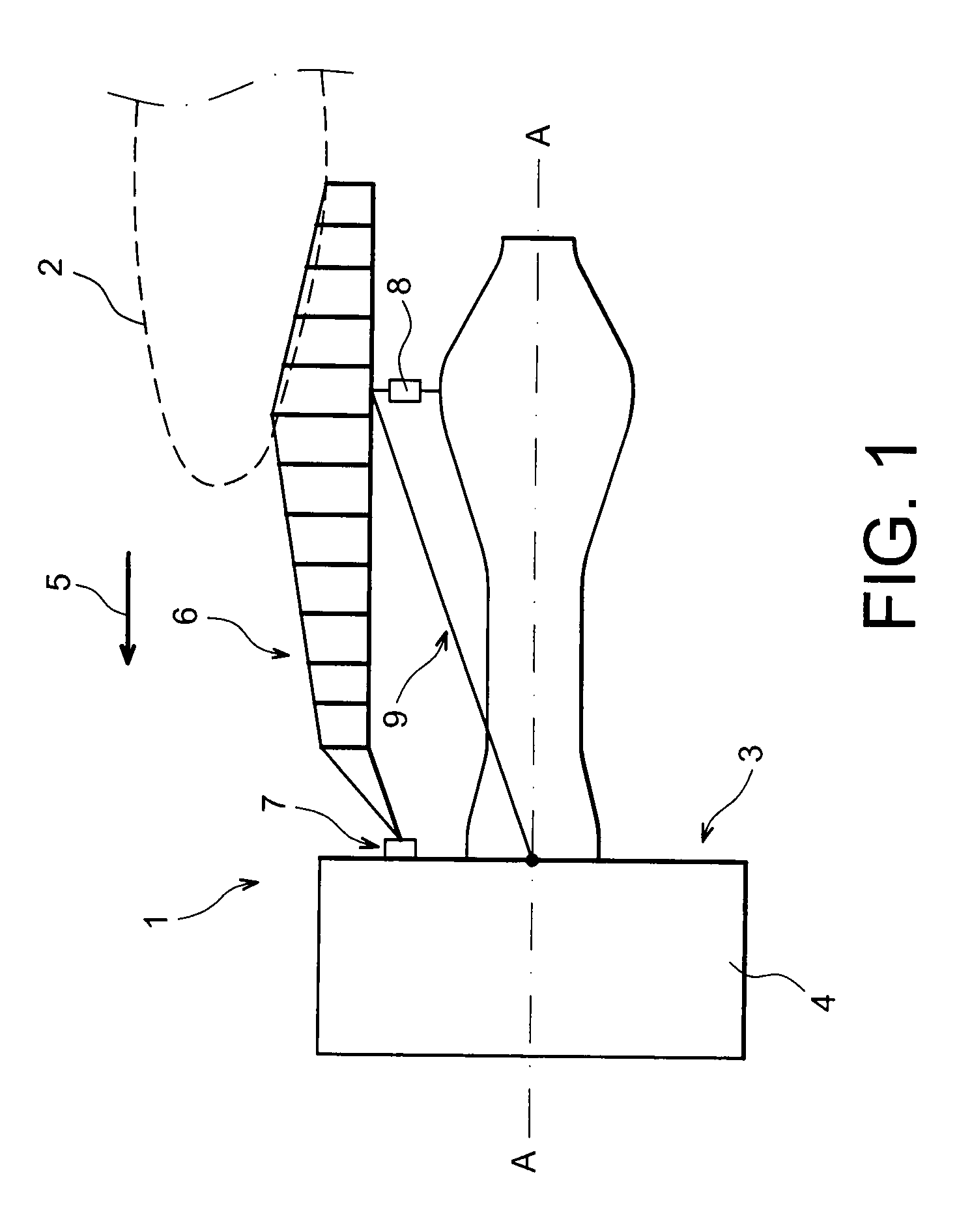
[0010]The invention proposes a novel structure for the aft engine attachment on the engine mount of an aircraft, which can lighten the device whilst maintaining its failsafe properties.
[0011]According to one of its aspects, the invention therefore proposes an engine attachment comprising a first device, or beam, intended to be secured to the engine mount, and two three-point shackles i.e. triangular brackets. The beam comprises a clevis provided with two branches in a U-shape, between which each shackle can be inserted. Each branch of the clevis comprises four opposite-facing anchor orifices, preferably only four holes, aligned if possible, which correspond to two orifices of each shackle; each shackle also comprises a third anchor orifice intended to be secured to a clevis on the engine side. Advantageously, the triangle formed by the three orifices of each shackle is an isosceles triangle.
[0012]The mounting of the engine attachment comprises the use of shackle pins, preferably bal...
PUM
 Abstract
Description
Claims
Application Information
 - R&D
- Intellectual Property
- Life Sciences
- Materials
- Tech Scout
- Unparalleled Data Quality
- Higher Quality Content
- 60% Fewer Hallucinations
Browse by: Latest US Patents, China's latest patents, Technical Efficacy Thesaurus, Application Domain, Technology Topic, Popular Technical Reports.
© 2025 PatSnap. All rights reserved.Legal|Privacy policy|Modern Slavery Act Transparency Statement|Sitemap|About US| Contact US: help@patsnap.com