
Muzzle loading firearm with break-open action

a technology of firearms and action, applied in the field of muzzle-loading firearms, can solve the problems of more difficult or slow inserting of primers, disadvantageous limit design options, and difficult or difficult pass-through cleaning, and achieve the effect of reducing the amount of residue/fouling extan

Active Publication Date: 2011-03-22
SMITH & WESSON
View PDF4 Cites 12 Cited by
  • Summary
  • Abstract
  • Description
  • Claims
  • Application Information

AI Technical Summary

Benefits of technology

"The present invention is a muzzle loading firearm with a break-open action. It includes a rear stock assembly and a barrel assembly that can be pivoted between an open position and a closed position. The barrel assembly is secured in the closed position by a breech block fixed to the stock assembly. The firearm also includes a user-actuated lever arm for moving the barrel assembly between the open and closed positions, and for securing the barrel assembly in the closed position. The breech plug is a hand-actuated rapid release plug that can be easily inserted and removed for cleaning or other access. The breech plug includes O-ring seals to reduce residue and fouling on the plug threads. The technical effects of the invention include improved user access, ease of cleaning, and reduced fouling on the breech plug threads."

Problems solved by technology

This makes it more difficult for pass-through cleaning, since the upper portion of the stock, located to the rear of the breech, limits access to the breech.
To provide unlimited access, the stock must be contoured to provide an access space, which may disadvantageously limit design options.
Furthermore, the stock portion adjacent to the breech may make it more difficult or slow to insert a new primer, and to access the breech for breech plug removal.
A further limitation of existing designs is that the process required for cleaning is somewhat cumbersome.
This can be somewhat difficult for the user, and risks damage.
Moreover, the receiver and other operational elements remain attached to the barrel, making cleaning less convenient.

Method used


Image

  • Muzzle loading firearm with break-open action
  • Muzzle loading firearm with break-open action
  • Muzzle loading firearm with break-open action

Examples


Embodiment Construction

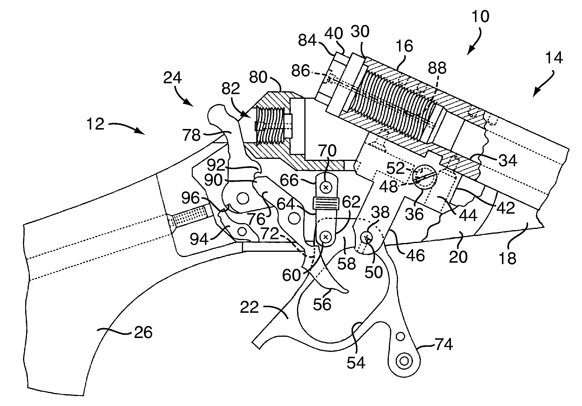
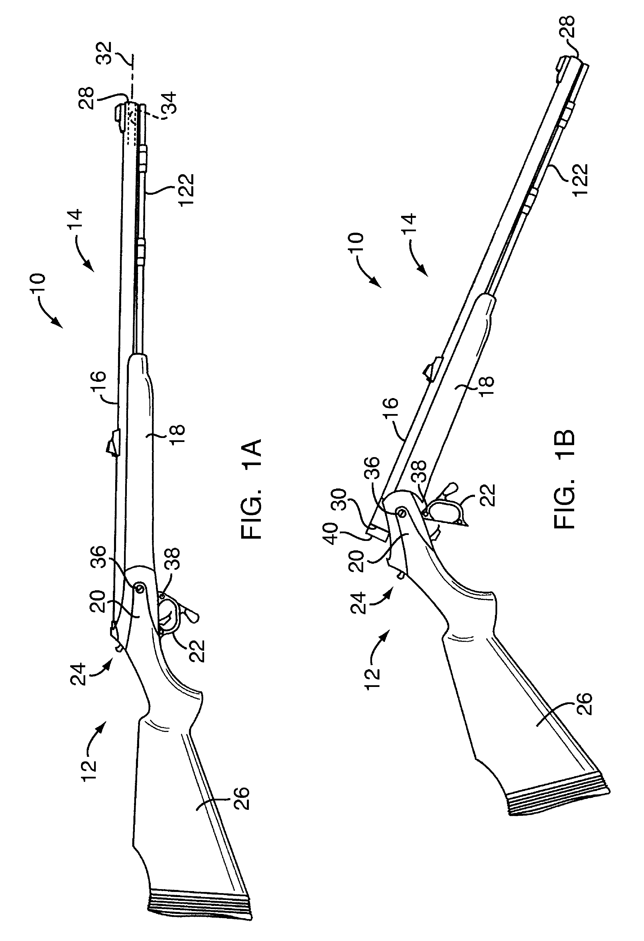
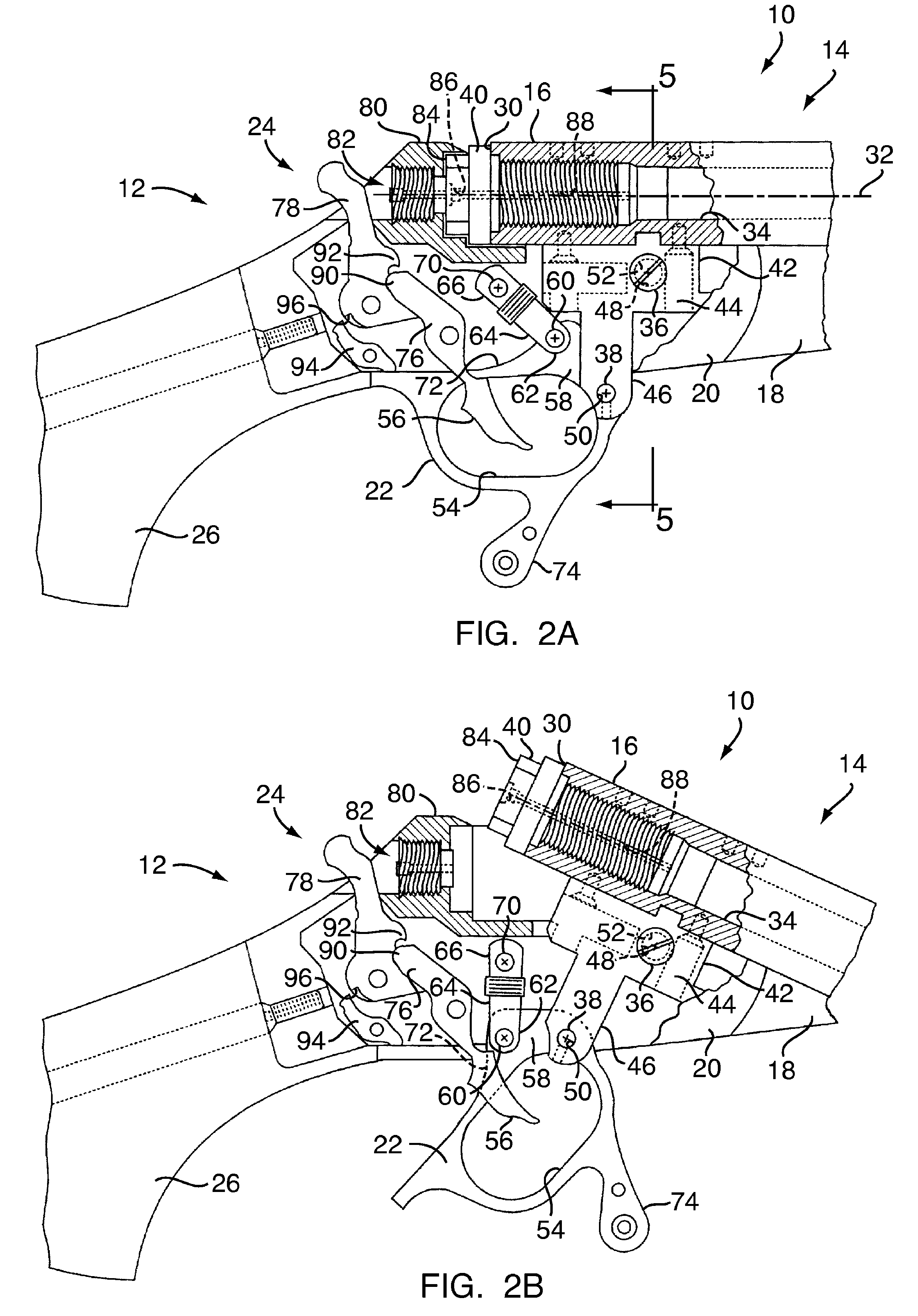
[0020]With reference to FIGS. 1A-10, an embodiment of the present invention relates to a muzzle loading handheld firearm 10 having a rear stock and support frame assembly 12 and a barrel assembly 14 pivotally linked to the stock assembly 12. The barrel assembly 14 includes a barrel 16 and a forestock 18 connected to the barrel. The stock assembly 12 includes a receiver or frame 20, a trigger guard 22, a firing mechanism 24, and a rear stock 26. The barrel 16 has a muzzle end face 28 and a breech end face 30, each perpendicular to an axis 32 defined by a rifled bore 34 extending longitudinally down the length of the barrel. The barrel assembly 14 is pivotally connected to the stock assembly 12 by a pivot bolt 36, and the trigger guard 22, acting as a user-actuated lever arm for moving the barrel assembly between closed and open positions, is pivotally connected to the barrel assembly 14 by a first removable pivot pin 38. A breech plug 40 encloses the breech end of the barrel 16, in a...


PUM

PropertyMeasurementUnit
movementaaaaaaaaaa
lengthaaaaaaaaaa
diameteraaaaaaaaaa

Abstract

A muzzle loading firearm with a break-open action includes a rear stock assembly and a barrel assembly. The barrel assembly includes an elongate barrel, having a bore with muzzle and breech ends, and a breech plug removably connected the breech end of the barrel, which encloses a chamber at the rear of the bore. The barrel assembly is pivotally attached to the rear stock assembly, and is movable with respect to the stock assembly between an open position in which the breech end is accessible for service, and a closed position in which the breech end is inaccessible and secured for discharge. A lever arm, optionally configured to serve as the firearm trigger guard, is user actuated for moving the action between the open and closed positions. The breech plug is configured for rapid removal from the barrel by hand when the action is open.

Description

FIELD OF THE INVENTION[0001]This invention relates to muzzle loading firearms and, more particularly, to mechanisms for opening firearm actions.BACKGROUND OF THE INVENTION[0002]Muzzle loading rifles have an essentially closed breech at the rear of the barrel, so that powder and projectiles must be loaded at the muzzle or forward end of the barrel. A typical muzzle loading rifle has a barrel with a breech plug attached to occupy an enlarged, internally threaded, rear bore portion of the barrel at the breech end. In some rifles, the breech plug is permanently attached. In others, the breech plug is removable to facilitate pass-through cleaning of the bore or similar operations.[0003]A conventional removable breech plug employs a finely threaded elongated body that screws into the rear of the barrel, which is internally threaded to receive the plug. Typically, ten to fifteen turns are required to secure the breech plug in place. The breech plug is not removed for normal loading operati...

Claims


Application Information

Patent Timeline
Patent Type & Authority Patents(United States)
IPC IPC(8): F41C9/08
CPCF41C7/11F41C9/08Y10T29/49826
Inventor LANEY, MARK C.ZGLOBICKI, MATTHEW
Owner SMITH & WESSON
Learn More