
Recovering servo information from a synchronous servo channel

a synchronous servo and tape drive technology, applied in the field of servo channel and tape drive for recovering servo information from a synchronous servo channel, can solve the problems of insufficient resolution, difficult extraction of timing information from the servo reader signal,

Inactive Publication Date: 2011-03-08
IBM CORP
View PDF4 Cites 16 Cited by
  • Summary
  • Abstract
  • Description
  • Claims
  • Application Information

AI Technical Summary

Benefits of technology

The patent describes a method, servo channel, and tape drive for recovering servo information from a synchronous servo channel. The method involves using an interpolator to read samples of a servo signal and produce interpolated servo samples. These samples are then buffered and outputted to a correlator to produce a correlation signal sample. The technical effect of this patent is to provide a more efficient and accurate way to recover servo information from a synchronous servo channel.

Problems solved by technology

Clearly, such a resolution is not adequate when one wants to detect LPOS bits with a modulation width of ±0.25 μm.
The extraction of timing information from the servo reader signal, however, is not straightforward, as the servo bursts into which a servo frame is subdivided, namely A, B, C, and D bursts comprising 5, 5, 4, and 4 dibits, respectively, are not equally spaced.

Method used


Image

  • Recovering servo information from a synchronous servo channel
  • Recovering servo information from a synchronous servo channel
  • Recovering servo information from a synchronous servo channel

Examples


embodiment details

Additional Embodiment Details

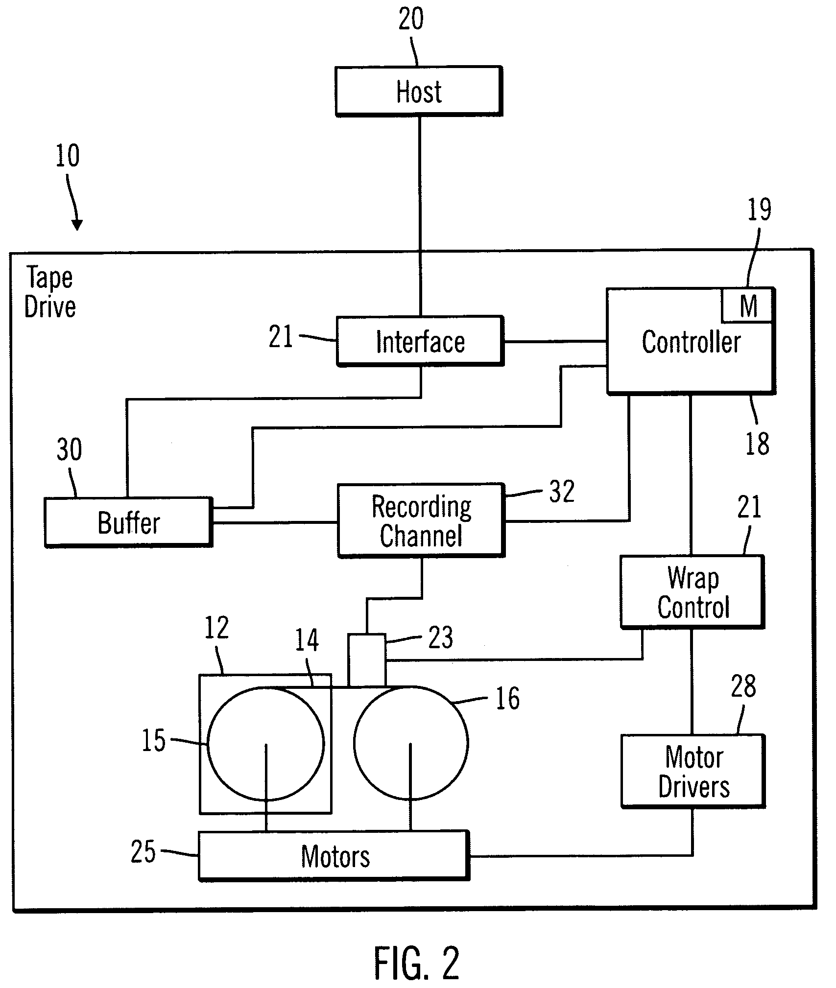
[0057]The described components of the servo channel 100, 200 described with respect to FIGS. 3 and 4 may comprise discrete logic, ASIC (application specific integrated circuit), FPGA (field programmable gate array), custom processors, etc.

[0058]The described components of the servo channel embodiments and the operations of the servo channel components described with respect to FIGS. 3 and 4 may alternatively be implemented in subroutines in programs or other software implementations executed by a processor. Such programs implementing the operations of the servo channel components described with respect to FIGS. 3 and 4 may be implemented in a computer readable medium, such as magnetic storage medium (e.g., hard disk drives, floppy disks, tape, etc.), optical storage (CD-ROMs, DVDs, optical disks, etc.), volatile and non-volatile memory devices (e.g., EEPROMs, ROMs, PROMs, RAMs, DRAMs, SRAMs, Flash Memory, firmware, programmable logic, etc.), etc. The cod...


PUM

PropertyMeasurementUnit
azimuth angleaaaaaaaaaa
velocityaaaaaaaaaa
timeaaaaaaaaaa

Abstract

Provided are a method, servo channel, and tape drive for recovering servo information from a synchronous servo channel. An interpolator reads samples of a servo signal obtained from a servo reader at a rate of one servo sample per clock interval, to produce up to M interpolated servo samples per clock interval. A first buffer buffers interpolation time instants at which the interpolator generates interpolated servo samples. The interpolated servo samples are buffered in a second buffer and the interpolated servo samples are outputted from the second buffer to a correlator to produce correlation signal samples.

Description

BACKGROUND[0001]1. Field[0002]The present invention relates to a method, servo channel, and tape drive for recovering servo information from a synchronous servo channel.[0003]2. Description of the Related Art[0004]In timing-based servo (TBS) systems, recorded servo patterns consist of magnetic transitions with two different azimuthal slopes. Head position is derived from the relative timing of pulses, or dibits, generated by a narrow head reading the servo patterns. TBS patterns also allow the encoding of additional longitudinal position (LPOS) information without affecting the generation of the transversal position error signal (PES). This is obtained by shifting transitions from their nominal pattern position using pulse-position modulation (PPM). Traditionally, the detection of LPOS information bits is based on the observation of the arrival times of the shifted dibit peaks within the servo bursts at the servo reader output. A specification for the servo format in current tape dr...

Claims


Application Information

Patent Timeline
Patent Type & Authority Patents(United States)
IPC IPC(8): G11B5/09
CPCG11B5/59644G11B20/10009G11B20/10037G11B20/10231G11B20/10527G11B2020/10759G11B2020/1281G11B2220/956
Inventor CHERUBINI, GIOVANNIHUTCHINS, ROBERT ALLENJELITTO, JENS
Owner IBM CORP
Learn More