
Digital video camera with binning or skipping correction

a digital video camera and correction technology, applied in the direction of television system, solid-state device signal generator, picture signal generator, etc., can solve the problems of reducing the quality of binning artifacts, and reducing the speed of ccd imaging sensors. achieve the effect of generating sharper images, reducing artifacts, and reducing artifacts

Active Publication Date: 2011-02-22
AMBARELLA INT LP
View PDF21 Cites 9 Cited by
  • Summary
  • Abstract
  • Description
  • Claims
  • Application Information

AI Technical Summary

Benefits of technology

The present invention is about a method and camera for generating video. The method involves using a camera to capture an optical signal, which is then converted to an electrical signal. The method includes steps to reduce the number of pixels in the signal, which can improve image quality. The camera can generate new pixels based on the original ones, resulting in sharper and smoother images. The technical effects of this invention include reducing artifacts caused by pixel binning and skipping, and generating higher quality images.

Problems solved by technology

CMOS and CCD imaging sensors are not fast enough to output all of the available pixels in a video frame time (i.e., 1 / 60th to 1 / 25th of a second).
The artifacts generated by skipping are commonly worse than the artifacts generated by binning.
Nonetheless, even binning artifacts are substantial.

Method used


Image

  • Digital video camera with binning or skipping correction
  • Digital video camera with binning or skipping correction
  • Digital video camera with binning or skipping correction

Examples


Embodiment Construction

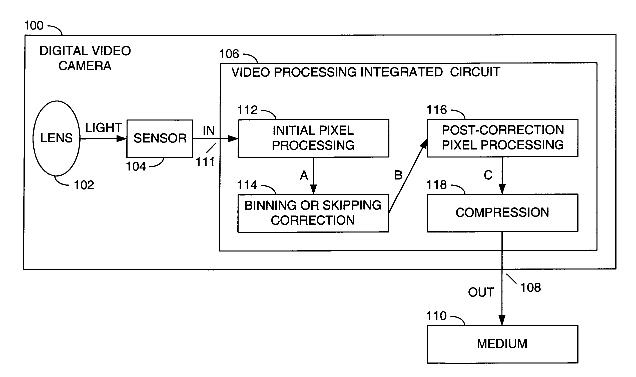
[0036]Referring to FIG. 5, a block diagram of example implementation of a camera 100 is shown in accordance with a preferred embodiment of the present invention. The camera 100 may be referred to as digital video camera. The digital video camera 100 generally comprises a lens 102, a sensor 104 and a circuit 106. An interface 108 may be provided in the digital video camera 100 to connect to a medium 110.

[0037]An optical signal (e.g., LIGHT) may be focused by the lens 102 onto the sensor 104. The sensor 104 generally produces Bayer pixels in a signal (e.g., IN) at an input 111 of the circuit 106. The pixels in the signal IN may be processed by the circuit 106 to generate a signal (e.g., OUT). The signal OUT may be transferred through the interface 108 to the medium 110 for storage, transmission and / or display.

[0038]An example implementation of the sensor 102 may be an MT9T001 3-megapixel digital image sensor available from Micron Technology, Inc., Bosie, Id. Operations of the MT9T001 ...


PUM


Abstract

A method of generating video and a video camera are disclosed. The method generally includes the steps of (A) generating an input signal by sensing an optical signal using a plurality of first pixels, wherein (i) the sensing is capable of a pixel reduction by at least one of binning the first pixels and skipping some of the first pixels and (ii) a plurality of first spatial separations among the first pixels in the input signal are (a) uniform both horizontally and vertically while the pixel reduction is inactive and (b) non-uniform while the pixel reduction is active, (B) generating a plurality of second pixels in response to the first pixels such that a plurality of second spatial separations among the second pixels are uniform both horizontally and vertically while the pixel reduction is active and (C) generating an output signal carrying the second pixels.

Description

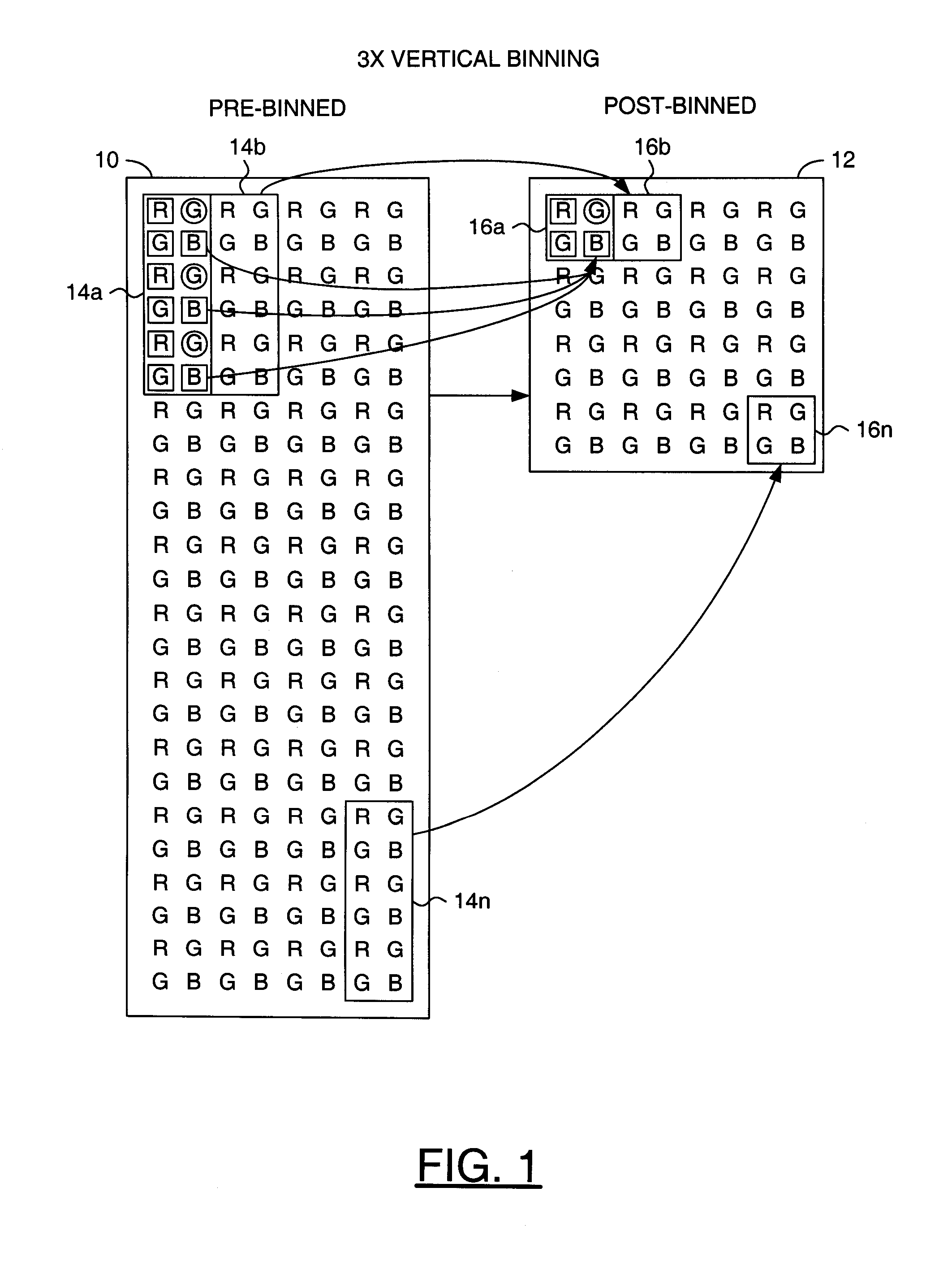
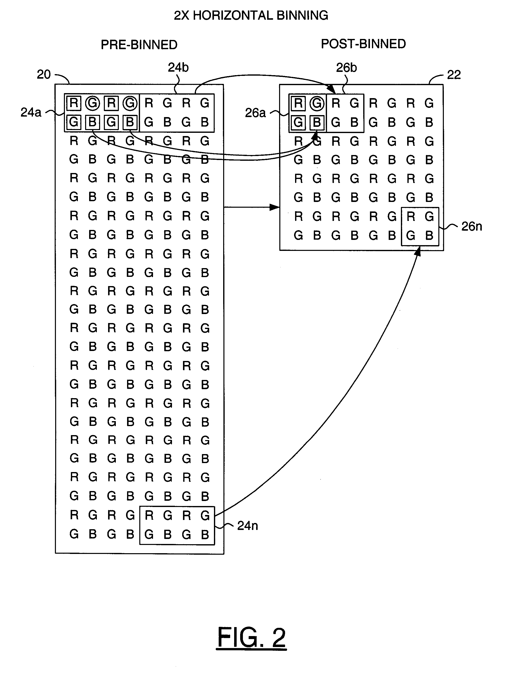
[0001]This is a continuation of U.S. Ser. No. 12 / 181,499, filed Jul. 29, 2008, which is a continuation of U.S. Ser. No. 11 / 034,034, filed Jan. 12, 2005, now U.S. Pat. No. 7,417,670 which are hereby incorporated by reference in their entirety.FIELD OF THE INVENTION[0002]The present invention relates to a method and / or architecture for video cameras generally and, more particularly, to a digital video camera with binning and / or skipping correction.BACKGROUND OF THE INVENTION[0003]Bayer pixels generated by an imaging sensor typically undergo a series of steps, including noise reduction, demosaicing and color space conversion, before being compressed into a compressed video signal. CMOS and CCD imaging sensors are not fast enough to output all of the available pixels in a video frame time (i.e., 1 / 60th to 1 / 25th of a second). In order to produce high frame rate video, the pixels are cropped, binned or skipped.[0004]Cropping is done to frame a picture per a user command and has a side ef...

Claims


Application Information

Patent Timeline
Patent Type & Authority Patents(United States)
IPC IPC(8): H04N5/228H04N23/40H04N25/00
CPCH04N5/3456H04N5/3458H04N5/347H04N5/357H04N9/045H04N25/445H04N25/46H04N25/447H04N23/843H04N25/68H04N25/60
Inventor LINZER, ELLIOT N.KWOK, WILSON
Owner AMBARELLA INT LP
Learn More