
Sheet switch module

a switch module and switch technology, applied in the direction of contacts, legends, light and heating apparatus, etc., can solve the problems of loss of light, reduced light-guiding efficiency throughout the entire light-guiding sheet, and reduced light-guiding efficiency

Inactive Publication Date: 2011-02-22
CITIZEN ELECTRONICS CO LTD
View PDF10 Cites 18 Cited by
  • Summary
  • Abstract
  • Description
  • Claims
  • Application Information

AI Technical Summary

Benefits of technology

Enhances light-guiding efficiency, maintains the operational feel of key presses, and prevents distortion of the light-guiding plate, thereby improving the overall performance and user experience of the switch module.

Problems solved by technology

Consequently, there is a problem that efficiency of light guided from the light source 8 through the light guiding plate 12 to each key top 14 is reduced.
However, in the conventional technology disclosed in above-mentioned Japanese Patent Application Publication No. 2007-53063, the light-guiding sheet 16 tends to curve at a boundary between the upper surface of the movable contact 6 and the upper surface of the circuit board 2, light is diffused at the curved portion thereby generating loss of the light, and there is a problem that light-guiding efficiency throughout the entire light-guiding sheet is reduced.

Method used


Image

  • Sheet switch module
  • Sheet switch module
  • Sheet switch module

Examples


Embodiment Construction

Preferred embodiments of the present invention will be explained in detail hereinafter with reference to the accompanying drawings.

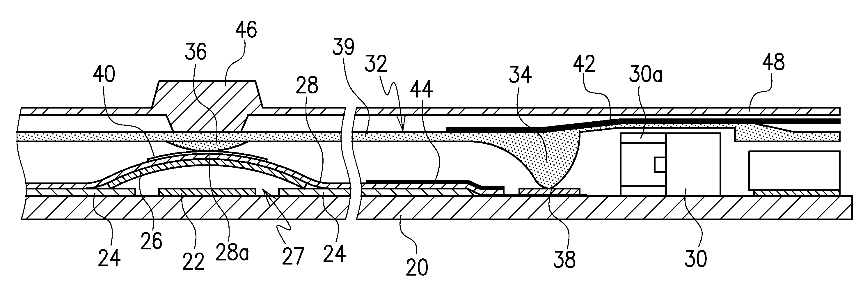
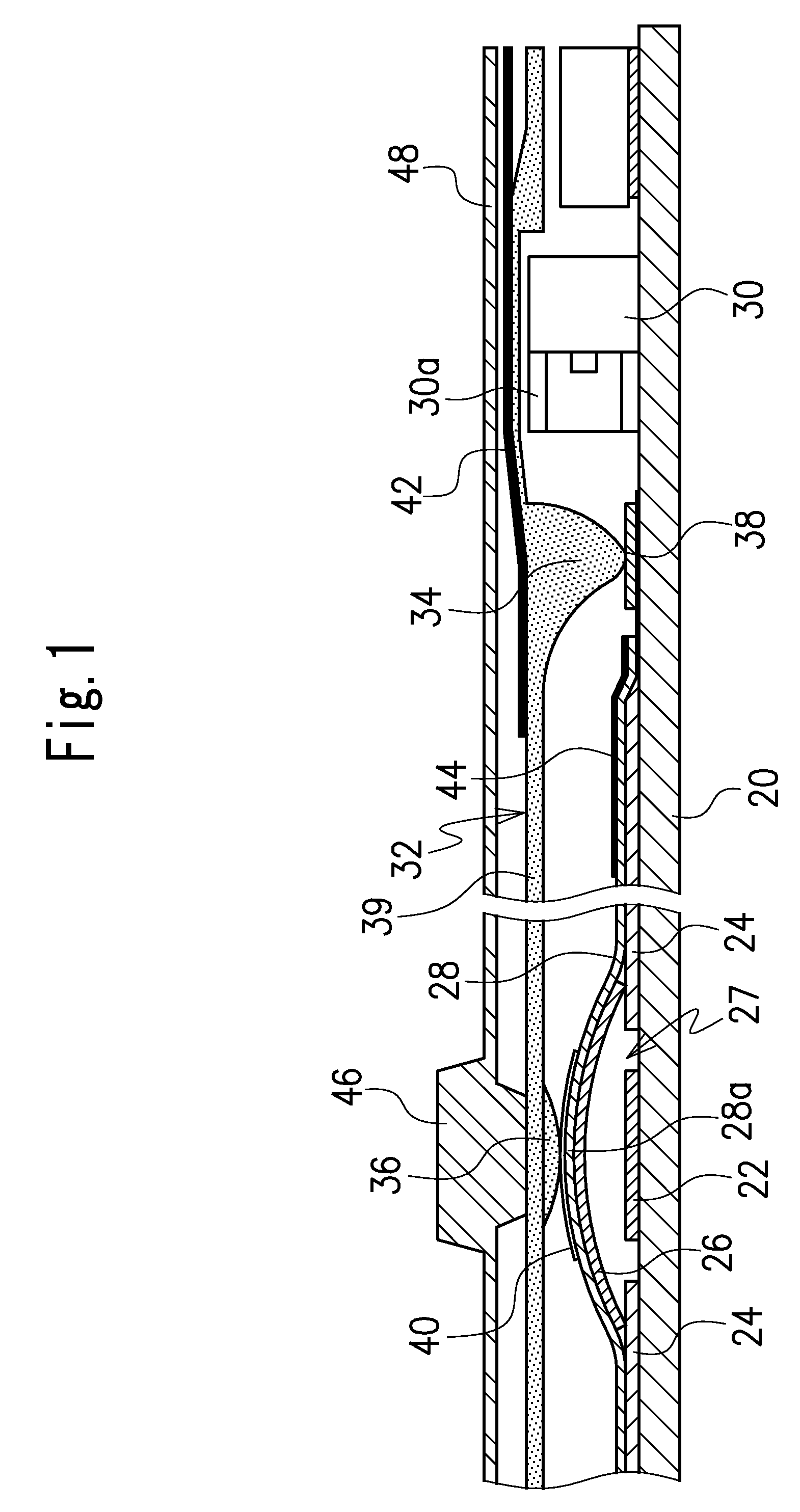
FIG. 1 illustrates a sheet switch module according to one embodiment of the present invention.

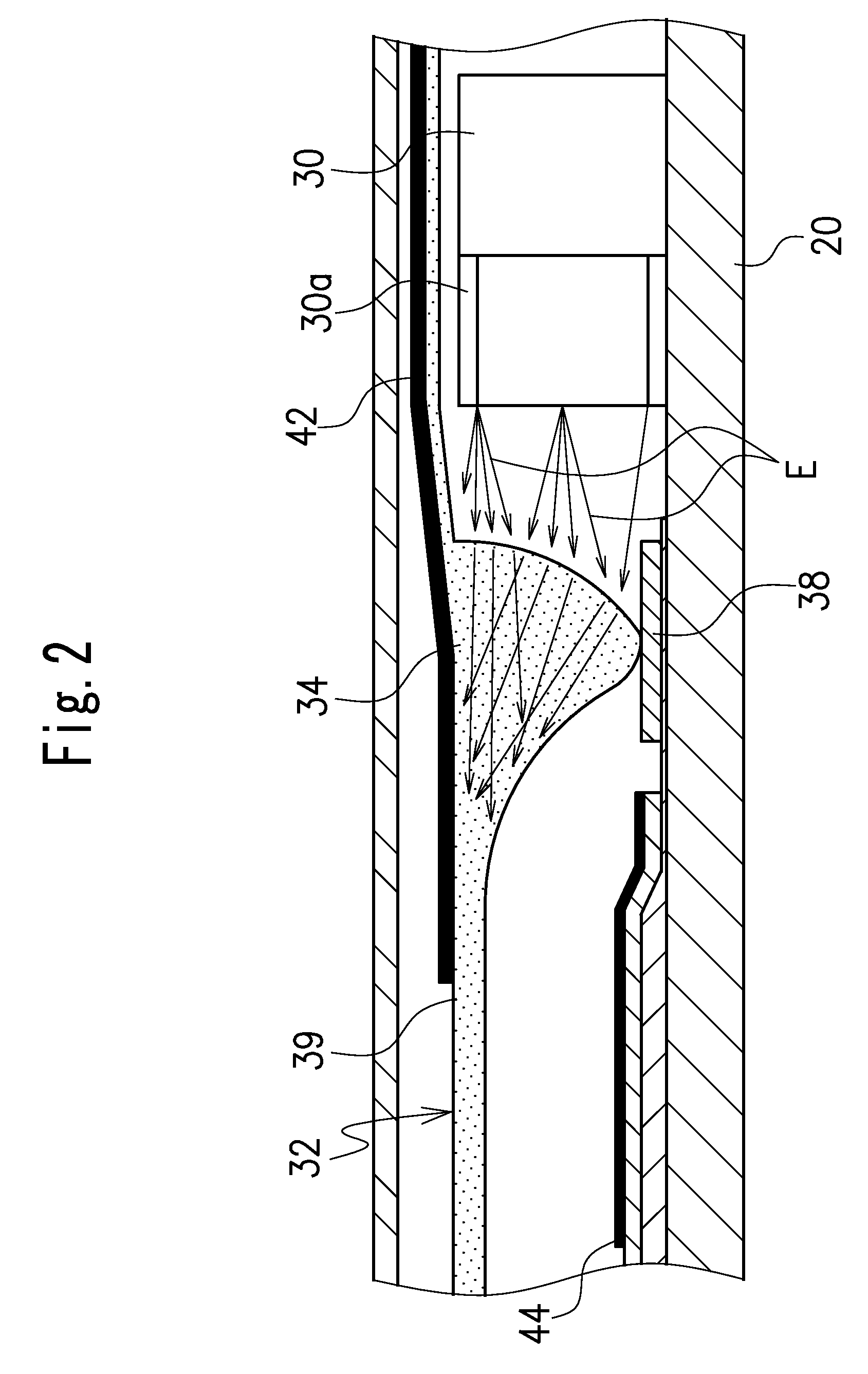
The sheet switch module in this embodiment includes a circuit board 20 formed by a flexible circuit board or the like and at least one switch 27 mounted on the circuit board 20. In the illustrated embodiment, a plurality of switches are provided on un upper surface of the circuit board 20. In this embodiment, each of the switches 27 includes a fixed contact 22 disposed on the upper surface of the circuit board 20 and a movable contact 26 which has a dome shape over the fixed contact 22 and has a peripheral edge disposed on and in contact with an electrode pattern 24 on the upper surface of the circuit board 20. The movable contact comprises, for example, a tact spring having a dome shape to achieve an electrical connection between the corresponding electrode pat...


PUM


Abstract

A sheet switch module includes a circuit board (20) provided with a fixed contact (22) thereon, a light source (30), a movable contact (26) to face the fixed contact (22), a sheet (28) to hold the movable contact (26) on the circuit board, a key top (46) disposed to face the movable contact and a light guiding plate (32) to guide light emitted from the light source (30) to the key top. The light-guiding plate (32) includes a light-receiving part (34) projecting toward an upper surface of the circuit board (20) and a light-guiding part (39). The light-guiding plate (32) is positioned in a substantially horizontal state supported by the light-receiving part (34) on the upper surface of the circuit board (20).

Description

CROSS-REFERENCE TO THE RELATED APPLICATIONThis application is based on and claims priority from Japanese Patent Application No. 2007-183817, filed on Jul. 13, 2007, the entire contents of which are hereby incorporated by reference.BACKGROUND OF THE INVENTION1. Field of the InventionThe present invention relates to a sheet switch module used in small electronic devices or the like such as mobile phones.2. Description of the Related ArtA conventional key switch used in small electronic devices or the like includes, as shown in FIG.5, a circuit board 2, a plurality of switches 10 provided on an upper surface of the circuit board 2, a plurality of light sources 8 mounted on the upper surface of the circuit board 2, and a light-guiding plate 12 disposed to cover the switches 10 (for reference, see Japanese Patent Application Publication No. 2007-53063, in particular FIG. 9).Each of the switches 10 includes a fixed contact 4 mounted on the upper surface of the circuit board 2 and a movabl...

Claims


Application Information

Patent Timeline
Patent Type & Authority Patents(United States)
IPC IPC(8): H01H9/00
CPCH01H13/83H01H2205/016H01H2219/044H01H2219/056H01H2219/062H01H2221/002H01H2221/05H01H2221/07
Inventor AIHARA, KENSHIMIYASHITA, ISAO
Owner CITIZEN ELECTRONICS CO LTD
Learn More